Monday, 28 May 2018

How to replace the mother board - Samsung Galaxy S5


Samsung Galaxy S5:  DISPLAY REPLACEMENT PROCEDURE 
Insert a fingernail or plastic opening tool into the divot to the left of the rear-facing camera. Gently pry and twist the flexible rear cover off the back of the phone.
Insert a fingernail or plastic opening tool into the recess in the bottom right corner of the battery and lift upward. Remove the battery away from the phone.
Using a fingertip, pull the microSD card straight down out of its slot. Remove the microSD card from the phone.
Repeat the above procedure to remove the SIM card.
Use a plastic opening tool to pry up the plastic midframe connector panel. Remove the connector panel with a pair of tweezers. There should be enough adhesive to readhere the panel upon reassembly, otherwise use a small amount of double-stick tape.
Use the sharp tip of a spudger to pry the home button cable connector straight up off its socket.
In the following steps you will be using an opening pick to separate the adhesive securing the front panel glass. Only pry where directed. If you experience resistance, stop sliding the opening pick and reapply heat. Insert the edge of an opening pick underneath the bottom right side of the front glass.
Slide the opening pick up along the right side of the display
Carefully slide the pick around the corner, stopping before the speaker grille at the top of the phone.
The adhesive securing the top of the phone is only a narrow strip above the earpiece speaker. Slide the pick along the top of the speaker to avoid damaging internal components. Slide the opening pick across the top of the phone, being very careful not to insert the pick too deeply.
Carefully slide the pick around the upper left corner. If you encounter any resistance from cooling adhesive, reapply a heated iOpener to the left side of the phone.
Slide the opening pick down along the left half of the phone stopping at the lower left corner.
Slide the opening pick all the way to the bottom left corner of the phone, making sure it is securely placed. In the following step you will be placing an iOpener over the home button end of the phone, you won't want your opening pick to slip out.
The bottom end of the phone contains the soft button and home button ribbon cables. If you insert the opening pick too far into the phone you risk cutting these cables. Slide the very end of the opening pick across the bottom edge of the display to separate the last of the remaining adhesive.
Twist the opening pick to detach the glass from the phone. If the front panel does not detach easily, it may require additional adhesive cutting.
If the front panel is not easily freed, the adhesive on the soft button cable may need to be separated. These cables are thin and easily damaged, therefore be certain you are only peeling them off the display assembly and not lacerating them. Insert an opening pick under the soft button icons on the display and pry the button cables down off the inside of the front panel.
Slightly lift, but do not remove, the home button end of display assembly. Do not remove the front panel entirely. It is still attached by a connector. If you are reusing the home button flex cable, be careful not to sever the cable from the home button. Adhesive can cause the cable to rip apart from the home button. While the home button will still work, the fingerprint scanner will not.
Use the sharp tip of a spudger to lift the front panel assembly cable connector straight up off its socket on the motherboard. Safely remove the front panel assembly from phone
Remove the ten 3.4 mm Phillips #000 screws from the display side of the midframe.
Flip the phone over and remove the following screws from the battery side of the midframe: Two 4.4 mm Phillips #000 screws near the USB port on the battery side of the phone
One 4.4 mm Phillips #000 screw
Gently run a plastic opening tool down along the left inner side of the interior frame to separate the three white plastic clips.
The midframe is composed of two halves that encase the motherboard. Gently pull the long sides of the silver bezel out away from the phone to separate the two halves of the midframe. It may be helpful to gently push in from the inside of the battery compartment, but be careful not to flex the interior half of the midframe, as the motherboard is mounted to it.
Continue on to the right side of the silver bezel, pulling away from the interior section of the midframe to separate the two halves.
Use a plastic opening tool to pry any remaining corners out of the silver bezel.
Carefully remove the interior midframe/motherboard assembly from the white inner midframe.
Carefully wedge the tip of a spudger underneath the antenna cable connector. Delicately lift the spudger directly upwards to disconnect the antenna connector off its socket on the motherboard.
Remove the single 3.0 mm Phillips #000 screw securing the motherboard to the midframe.
Pull, but do not remove, the camera end of the motherboard up from the midframe to allow access to the connectors on the rear. Do not attempt to fully remove the motherboard as it is still attached to the interior midframe by the Micro-USB port daughterboard connector.
Use the flat end of a spudger to pry the daughterboard connector straight up off its socket on the motherboard.
Use the flat end of a spudger to disconnect the front-facing camera connector off its socket on the motherboard. Remove the front-facing camera from the motherboard.
Use the flat end of a spudger to disengage the rear-facing camera connector straight up off its socket on the motherboard. Remove the rear-facing camera from the motherboard.

Sunday, 27 May 2018

HP 2760p EliteBook – Disassembling procedure – How to remove the keyboard – How to remove HDD – How to remove the battery


HP 2760p EliteBook:  DISASSEMBLING PROCEDURE 
How to remove Battery
Before disassembling the computer, follow these steps:
1. Shut down the computer. If you are unsure whether the computer is off or in Hibernation, turn the computer on, and then shut it down through the operating system.
2. Disconnect all external devices connected to the computer.
3. Disconnect the power from the computer by first unplugging the power cord from the AC outlet, and then unplugging the AC adapter from the computer.
Remove the battery:
1. Turn the computer upside-down on a flat surface, with the battery bay toward you.
2. Slide the battery release latch to release the battery.
3. Pivot the edge of the battery upward and remove it from the computer.
How to remove Service access cover
Before removing the service access cover, follow these steps:
1. Shut down the computer. If you are unsure whether the computer is off or in Hibernation, turn the computer on, and then shut it down through the operating system.
2. Disconnect all external devices connected to the computer.
3. Disconnect the power from the computer by first unplugging the power cord from the AC outlet, and then unplugging the AC adapter from the computer.
4. Remove the battery
Remove the service access cover:
1. Position the computer upside-down, with the front toward you.
2. Loosen the three Phillips M2.0x3.0 captive screws that secure the service access cover to the computer.
3. Lift the rear edge of the service access cover until it rests at an angle, and then remove the cover.
How to remove Hard drive
Before removing the hard drive, follow these steps:
1. Shut down the computer. If you are unsure whether the computer is off or in Hibernation, turn the computer on, and then shut it down through the operating system.
2. Disconnect all external devices connected to the computer.
3. Disconnect the power from the computer by first unplugging the power cord from the AC outlet, and then unplugging the AC adapter from the computer.
4. Remove the following components:
a. Remove the battery
b. Remove the service access cover .
Remove the hard drive:
1. Loosen the Phillips M2.5×8.0 captive screw (1) that secures the hard drive bracket to the computer.
2. Grasp the tab on the hard drive and slide it forward to disconnect the hard drive.
3. Lift the hard drive (2) to remove it from the computer.
How to remove Keyboard
Before removing the keyboard, follow these steps:
1. Shut down the computer. If you are unsure whether the computer is off or in Hibernation, turn the computer on, and then shut it down through the operating system.
2. Disconnect all external devices connected to the computer.
3. Disconnect the power from the computer by first unplugging the power cord from the AC outlet, and then unplugging the AC adapter from the computer.
4. Remove the following components:
a. Remove the battery
b. Remove this service access cover
Remove the keyboard:
1. Turn the computer upside-down, with the front toward you.
2. Remove the two screw caps and loosen the five captive screws that secure the keyboard to the computer.
3. Turn the computer right-side up, with the front toward you.
4. Open the display as far as possible.
5. Insert a flat tool under the back edge of the keyboard near the display hinge. Gently lift the rear edge of the keyboard and disconnect the keyboard.
6. Holding the keyboard at an angle, lift the keyboard far enough to gain access to the cables underneath and release the zero insertion force (ZIF) connector to which the pointing stick cable is attached to the system board and remove the pointing stick ZIF cable (3) from the connector.
7. Flip the keyboard over to the left and lay it flat then release the ZIF connector that secures the keyboard cable to the system board and remove the keyboard cable from the ZIF connector.
8. Release the ZIF connector to which the pointing stick cable is attached, and then disconnect the cable from the keyboard.

Lenovo ThinkPad P40 Yoga – How to replace the keyboard


Lenovo ThinkPad P40 Yoga – How to replace the keyboard – How to test the power supply – How to test the battery pack
Lenovo ThinkPad P40 Yoga:  Power system checkout
To verify a power symptom, do the following:
1. Turn off the computer.
2. Connect the ac power adapter.
3. Turn on the computer. If the computer can be turned on, it means that either the battery pack or the ac power adapter is functional.
4. Insert a straightened paper clip into the emergency reset hole to reset the computer. If the computer is still powered on, it means that the ac power adapter is functional.
5. Turn off the computer.
6. Disconnect the ac power adapter and turn on the computer. If the computer can be turned on, it means that the battery pack is functional.
If you suspect a power problem, see the appropriate one of the following power supply checkouts:
“Checking the ac power adapter”
“Checking the built-in battery and operational charging”
“Checking the coin-cell battery”
Checking the ac power adapter
You are here because the computer fails only when the ac power adapter is used.
If the power problem occurs only when the docking station or the port replicator is used, replace the docking station or the port replicator.
If the system-status indicator does not blink three times when an ac power source is connected, check the power cord of the ac power adapter for correct continuity and installation.
To check the ac power adapter, do the following:
1. Unplug the ac power adapter cable from the computer.
2. Measure the output voltage at the plug of the ac power adapter cable. See the following illustration:
Note: Output voltage of pin 2 of the ac power adapter might differ from the one you are servicing.
3. If the voltage is not correct, replace the ac power adapter.
4. If the voltage is acceptable, replace the system board.
Note: Noise from the ac power adapter does not always indicate a defect.
Checking the built-in battery and operational charging
To check whether the battery charges properly during operation, do the following:
1. Discharge the battery until the remained battery power is less than 50%.
2. Connect the computer to ac power to charge the battery. If the battery status icon in the Windows notification area indicates that the battery is not charging, remove the battery and let it return to room temperature.
3. Reinstall the battery. If the battery is still not charging, replace the battery pack.
4. Check the battery status icon again. If the same error still exists, replace the system board.
Checking the coin-cell battery
To check the coin-cell battery, do the following:
1. Disconnect the battery connector.
2. Remove the coin-cell battery.
3. Measure the voltage of the coin-cell battery. See the following illustration.
If the voltage is correct, replace the system board.
If the voltage is not correct, replace the coin-cell battery.
If the coin-cell battery discharges quickly after replacement, replace the system board.
How to remove the Keyboard
Remove the screws that secure the keyboard.
Push hard in the direction shown by the arrows to unlatch the front edge of the keyboard (the edge that is close to you).
Note: Depending on the model, your computer might look different from the following illustration.
Pivot the keyboard slightly upward as shown by the arrow .Then turn over the keyboard as shown by the arrow.
Note: Depending on the model, your computer might look different from the following illustration.
Detach the connectors and remove the keyboard.

BlackBerry Z10 – Disassembling procedure – How to remove the case – How to remove the battery – How to replace the Screen


Turn the phone over so that the back cover faces up. Locate the groove at the bottom center of the phone. Press the groove with your thumb to release the edge of the case from the phone.
Use your thumb and index finger to carefully open the sides of the phone. Start from the bottom and work your fingers up along the sides of the phone until the back cover is completely separated from the body of the phone.
Lift the bottom corner of the battery with your fingers. Remove the battery from the body of the phone.
Use a T3 or T4 (sub-models vary) Torx screwdriver to remove the nine screws shown in the picture. Keep the screws in a safe place.
Gently lift the plastic housing off the phone and set it aside. You can now see the motherboard.
Use the spudger to detach the green flat-top connector located under the rear camera. Slowly push the connector up and back. Refer to the first and second images. Use the spudger to detach and lift the orange flat-top connector seen in the second image. Slowly push the connector up and back. Then, detach the remaining two flat-top connectors one at a time to release the motherboard from the housing.
The motherboard is fragile. Make sure all connectors have been detached before you remove the motherboard. Carefully remove the motherboard and set it aside on an antistatic surface. Depending on the part you bought, you may be able to skip the remaining steps. A complete screen and case assembly can be purchased together. If that's what you have, simply move the motherboard to the new piece and reverse the steps above to reassemble your device. Otherwise, continue with the steps below.
The screen is fragile and may crack if the screws are not removed carefully. Use a T2 Torx screwdriver to remove the first small screw located at the top right. Refer to the second image. Then unscrew the four screws that surround the case. Refer to the third image. Keep all five screws in a safe place.
Turn the phone over so that the touch screen faces you. Slide a plastic opening tool around the rectangular edge of the phone to separate the touch screen from the case. Start from either of the bottom corners and work your way around the phone to loosen the screen. The connectors are connected to the phone case. Be careful not to damage them when you separate the screen from the phone case. Gently separate the screen from the phone case. Now, the phone is ready for a new screen.

How to replace the Noisy fan of Sony Playstation 3


Noisy Fan – Sony Playstation 3 
Turn the PS3 over and lay it on its backside.
Carefully peel the warranty sticker up off the lower case to reveal a hidden screw cover.
To avoid activating the VOID that may come up, heat the sticker carefully to remove and replace it cleanly.
Use the flat end of a metal spudger to pry up the seven screw covers around the edge of the lower case.
Remove the seven 37 mm Phillips screws securing the top cover to the lower case.
Remove the four 13.3 mm T8 security Torx screws beneath the Blu-ray drive opening. (Some models may only have three screws)
Lift the top cover from its rear edge and rotate it toward the front of the PS3.
Lift the top cover off the PS3.
 Squeeze the AC inlet connector's locking mechanism and pull straight up to disconnect it from the power supply.
Pull the DC-Out cables straight up to lift their connector up and out of its socket on the power supply.
 Remove the two 7.6 mm Phillips screws securing the power supply to the lower case.
Lift the power supply upward from its left edge as viewed from the front of the PS3.
 Continue to lift the left edge of the power supply until it lifts off the two metal posts shown in the second picture.
Remove the power supply from the PS3, minding any cables that may get caught.
Pull the fan cables upward to lift the fan connector up and out of its socket on the motherboard.
De-route the fan cables from under the plastic hook molded into the fan shroud.
 Remove the two 9.5 mm Phillips screws securing the fan to the heat sink.
 Lift the fan out of the heat sink, minding any cables that may get caught.

Mitsubishi Electric WL7200U – LCD PROJECTOR – How to replace the lamp – How to reset the lamp hour Timer


Mitsubishi Electric WL7200U – LCD PROJECTOR – How to replace the lamp – How to reset the lamp hour Timer  - How to Replace the roller filter – Roller filter counter reset
Mitsubishi Electric WL7200U:  How to replace the lamp
1. Unplug the power cord.
2. Loosen two screws (a) that are securing the lamp cover using a Philips screwdriver and remove the lamp cover (b) from the projector.
3. Loosen two screws (c) that are securing the lamp box to be removed using a Philips screwdriver.
4. Pull out the lamp box by the handle while holding the projector.
# Pull the lamp box out of the projector slowly. When the lamp is broken, glass fragments may be scattering by quickly pulling out the lamp box.
# Do not spill liquid on the removed lamp box or do not place it near any flammable object or where children can reach to prevent injury or fire.
5. Load a new lamp box securely into the projector in the right orientation.
6. Tighten two screws (c) of the new lamp box tightly using a Philips screwdriver.
# Make sure that the screws are tightened firmly.
7. Insert the lamp cover (b) into the projector and tighten two screws (a) on the lamp cover firmly using a Philips screwdriver.
# You cannot turn on the projector without attaching the lamp cover.
Reset of the lamp operation time
Plug in the power cord and reset the lamp operation time by holding down the LEFT,RIGHT, and POWER buttons on the control panel at the same time about 3 seconds.
Important:
# Unless these 3 buttons are pressed at the same time, the lamp operation time isn’t reset.
# Make sure that the STATUS indicator blinks twice and the lamp operation time is reset successfully.
# The projector doesn’t turn on if the lamp cover isn’t attached securely.
# Be sure to reset the lamp operation time whenever you replace the lamp.
# Do not reset the lamp operation time unless you replace the lamp.
# The lamp is fragile. If it is broken, be careful not to cut yourself with glass fragments.
Cleaning of the projector and the ventilation slots
Use a soft cloth to clean the projector and the ventilation grilles. When the grilles become dirty, wipe them with a soft
cloth dampened with diluted mild detergent, and then wipe them with a dry cloth.
# Clean the inside of the terminal cover frequently as dust is apt to be collected.
To protect the surface of the projector from fading or deteriorating:
# Do not spray insecticide on or inside the projector.
# Do not use benzine or thinner to clean it.
# Do not let rubber or plastic materials contact with projector.
Cleaning of the lens
Use a standard lens-cleaning brush or a piece of lens tissue dampened with lens cleaning fluid. The lens surface is
fragile. Use only recommended, nonabrasive lens-cleaning materials. Do not touch the lens with your fingers.
Roll-up filter
Setting the roll interval
You can set the roll interval of the roll-up filter using the menu.
1. Display the FEATURE menu.
2. Select FILTER MENU by pressing the UP or DOWN button.
3. Press the ENTER button.
4. Select AUTO ROLL UP PERIOD by pressing the UP or DOWN button.
5. Select OFF, EVERY 500H, EVERY 750H or EVERY 1000H by pressing the RIGHT or LEFT button.
OFF.................The filter does not roll automatically. Roll the filter manually when the filter is clogged.
EVERY 500H...The filter rolls about every 500 hours.
EVERY 750H...The filter rolls about every 750 hours.
EVERY 1000H..The filter rolls about every 1000 hours.
Important:
If you select the interval which is shorter than the current filter usage time, the filter rolls once after 1 minute.
The manual roll-up
1. Display the FEATURE menu.
2. Select FILTER MENU by pressing the UP or DOWN button.
3. Press the ENTER button.
4. Select MANUAL ROLL UP by pressing the UP or DOWN button.
5. Press the ENTER button.
Confirmation dialog appears.
6. Press the ENTER button or MENU button.
When you press the ENTER button, the filter rolls once.
To cancel the setting, press the MENU button.
How to replace the roll-up filter
When the filter rolls 9 times, the FILTER indicator blinks red. In this case, prepare a new filter cartridge. When the last filter is clogged, replace the filter cartridge. Before replacing the filter, be sure to turn off the power of the projector and unplug the power cord from the outlet.
1. Unplug the power cord.
2. Loosen two screws (a) that is securing the filter cover using a Philips screwdriver and remove the filter cover (b) from the projector.
3. Remove the roll-up filter cartridge.
5. Insert the filter cover (b) into the projector and tighten two screws (a) on the filter cover firmly using a Philips screwdriver
Reset of the roll counter of the filter
Plug in the power cord and reset the roll counter of the filter (REMAINING FILTERS and FILTER USAGE TIME) by holding down the LEFT, RIGHT and ENTER/GEOMETRY buttons on the control panel at the same time about 3 seconds.
Important:
# Unless these 3 buttons are pressed at the same time, the counter isn’t reset.
# Make sure that the FILTER indicator blinks 3 times and the counter is reset successfully.
# The projector doesn’t turn on if the filter cartridge or the filter cover isn’t attached securely.
# Do not reset the counter unless you replace the filter cartridge.

Friday, 25 May 2018

Motus USA Elliptical Cross Trainers M770E - M770EL – How to adjust Belt – How remove the rear cover – How to replace the belt


Motus USA Elliptical Cross Trainers M770E - M770EL:  How to Replace the REAR COVER
1) The following tools are required.
Philips Screw Driver, Wrench Sets, Snap Ring Pliers
2) Remove two BUTTON CROSS BOLT securing left REAR COVER-L (133) to right REAR COVER-R
3) Remove two BUTTON CROSS BOLT  and two ALLEN BOLT  securing left REAR COVER-L  to the Frame, and then remove left REAR COVER-L.
4) Remove two BUTTON CROSS BOLT  and two ALLEN BOLT  securing right REAR COVER-R  to the Frame, and then remove right REAR COVER-R
5) Remove six BUTTON CROSS BOLT  and then lift REAR COVER-C  up.
6) Replace the specific part
7) Install the REAR COVER-C, REAR COVER-R and REAR COVER-L in reverse order.
How to Adjust the Drive Belt (or Pulley Belt) Tension
1) Loosen two HEX LOCK NUTs  a little using 17mm spanner.
2) To increase the tension, turn HEX NUT  clockwise with a 19mm spanner while holding H/S HEX BOLT  with another 19mm spanner. Initial tension is set to 190 Hz. To decrease the tension, turn HEX NUT  counterclockwise.
3) Make sure that PULLEY BELT does not slip and then install the REAR COVER-C, REAR COVER-R and REAR COVER-L in reverse order.
How to Replace the Drive Belt (or Pulley Belt)
1) Loosen two HEX LOCK NUTs  a little using 17mm spanner.
2) To loosen the PULLEY BELT , turn HEX NUT (21) counterclockwise with a 19mm spanner while holding H/S HEX BOLT  with another 19mm spanner.
3) Derail the slackened PULLEY BELT  from the PULLEY.
4) Remove CAP HEX NUT  and PLANE WASHER  using 24 mm spanner.
5) Pull COUPLER FRAME  out of CRANK ASS’Y-230  by lifting it off.
6) Remove H/S HEX BOLT  and HEX LOCK NUT  using 21 mm Spanner and then slide CRANK ASS’Y-230  off the Shaft of the Pulley
7) Remove SQUARE KEY  from the Shaft.
8) Remove four H/S HEX BOLTs  using 17 mm spanner and then slide the BEARINGUCF206  off the Frame and Shaft of the Pulley.
9) To remove the CRANK ASS’Y-230 and BEARING-UCF206 in opposite side, repeat the same procedures as (4) thru 8).
10) Remove the PULLEY  combined with the Shaft by taking it out toward the front of the Machine.
11) Remove the PULLEY BELT.
12) Install the new PULLETY BELT in reverse order.
13) If needed, adjust the Pulley Belt Tension.”
How to Replace the Generator
1) Disconnect two cables from the GENERATOR.
2) Loosen two HEX LOCK NUTs  a little using 17mm spanner.
3) To loosen the PULLEY BELT , turn HEX NUT  counterclockwise with a 19mm spanner while holding H/S HEX BOLT  with another 19mm spanner.
4) Derail the slackened PULLEY BELT  from the PULLEY.
5) Remove ALLEN BOLT , HEX LOCK NUT  and PLANE WASHER  securing the GENERATOR  to the GENERATOR FRAME  by using 4mm wrench and 10 mm spanner.
6) Remove the GENERATOR  from the GENERATOR FRAME
7) Install new the GENERATOR  in reverse order.
8) If needed, adjust the Pulley Belt Tension.
How to Replace the UNIT BEARING – UCF206
The procedure to replace the Bearing is same on both right side and left side.
1) Loosen two HEX LOCK NUTs  a little using 17mm spanner.
2) To loosen the PULLEY BELT , turn HEX NUT (21) counterclockwise with a 19mm spanner while holding H/S HEX BOLT  with another 19mm spanner.
3) Derail the slackened PULLEY BELT  from the PULLEY.
4) Remove CAP HEX NUT  and PLANE WASHER  using 24 mm spanner.
5) Pull COUPLER FRAME  out of CRANK ASS’Y-230  by lifting it off.
6) Remove H/S HEX BOLT  and HEX LOCK NUT  using 21 mm spanner and then slide CRANK ASS’Y-230  off the Shaft  of the Pulley.
7) Remove SQUARE KEY  from the Shaft.
8) Remove four H/S HEX BOLTs  using 17 mm spanner and then slide the BEARINGUCF206  off the SHAFT ASS’Y.
9) Install new BEARING-UCF206  in reverse order.
10) If needed, adjust the Pulley Belt Tension.
How to Replace the CRANK ASSEMBLY
1) Loosen two HEX LOCK NUTs  a little using 17mm spanner.
2) To loosen the PULLEY BELT , turn HEX NUT  counterclockwise with a 19mm spanner while holding H/S HEX BOLT  with another 19mm spanner.
3) Derail the slackened PULLEY BELT from the PULLEY
4) Remove CAP HEX NUT  and PLANE WASHER  using 24 mm spanner.
5) Pull COUPLER FRAME  out of CRANK ASS’Y-230  by lifting it off.
6) Remove H/S HEX BOLT and HEX LOCK NUT  using 21 mm spanner and then slide CRANK ASS’Y-230  off the Shaft  of the Pulley.
7) Install new CRANK ASS’Y-230  in reverse order.

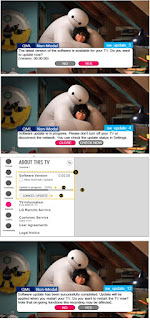
LG 32LK610BPUA, LG 32LK610BBUA LCD TVs – How to upgrade the software, fault checking method

  Software update procedure USB (1) Insert the USB memory Stick to the USB port (2) Automatically detect the SW Version and show the bel...