Lenovo YOGA
Tablet 2-851F
To verify a symptom, follow the
steps below:
1. Turn off the computer.
2. Remove the battery pack.
3. Connect the AC adapter.
4. Make sure that power is supplied when you turn on the computer.
5. Turn off the computer.
6. Disconnect the AC adapter and install the charged battery pack.
7. Make sure that the battery pack supplies power when you turn on the computer.
If you suspect a power problem, see the appropriate one of the following power supply checkouts:
“Checking the Computer AC Charger”
“Checking the internal battery status”
Checking the Computer AC Charger
When you use the computer AC Charger to charge the tablet but no power is charged, see the instructions in this topic to check the computer AC Charger.
To check the computer AC Charger, do the following:
1. Disconnect the micro-USB cable from the tablet.
2. Measure the output voltage across the connector marked B of the micro-USB cable. Refer to the following figure:
Note: The output voltage
across pin 3 of the micro-B connector might be different from the one you are
servicing.


3. If the voltage is not correct,
replace the micro-USB cable.
4. If the voltage is acceptable, replace the system board.
Checking the internal battery
status
To check the battery status of the tablet, do either of the following:
Approximate information about the battery status
Get the approximate status of the battery at any time by checking the battery status icon on the system bar in the upper-right corner of the screen. The shorter the green bar is, the less the battery power remains.
Accurate information about the battery status
To get the accurate information about the battery status of the tablet, do the following:
1. Open the Android Settings screen.
To open the Android Settings screen, do either of the following:
From the main Home screen, touch the Android Settings icon on
Lenovo Launch Zone. The Android Settings screen is displayed.
Pull down the application icon from the action bar and then touch Settings. The Android Settings screen is displayed.
2. Touch Battery in the Device section on the Android Settings screen.
3. The accurate percentage of the remaining battery power is shown on the screen.
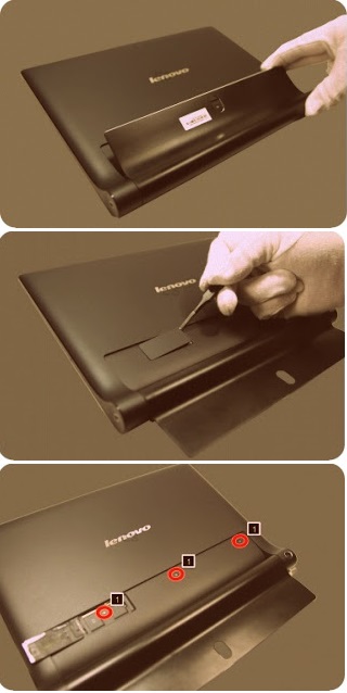

Disassembling procedure
How to remove Rear cover
1. Open the hinge frame.
1. Open the hinge frame.
2. Open the card slot cover using
a thin flat blade or guitar pick.
3. Remove screws 1 on the rear
cover as shown in the figure below.
4. Separate the bottom right
corner of the rear cover from the main body of the tablet using a suction tool
as shown in the figure below.
5. Hold the tablet in one hand
and use a guitar pick to unlock the rear cover from the tablet along the joint
line as shown in the figure below.
6. Slowly remove the rear cover.