Saturday 29 December 2018

Samsung PDP – PA43H4100AR – how to enter the service mode, troubleshooting, pin voltages and more…


Troubleshooting
* Check the various cable connections frst.
* Check to see if there is a burnt or damaged cable.
* Check to see if there is a disconnected or loose cable connection.
* Check to see if the cables are connected according to the connection diagram.
2) Check the power input to the Main Board.
3) How to distinguish if the problem is caused by Main board or Logic Board.
 No Video
If the problem is No Video but Logic Board is on and Indication LED is blinking repeatedly and faster than nomal booting, replace the Main/Logic board.
 Distorted Picture: Check the Logic test patterns.
How to check Logic test pattern
a) Entering Factory mode.
b) Move to SVC menu.
c) Move to Test Pattern.
d) Move to Test Pattern.
LED blinking codes

LED blink time is once per 0.5s – Normal.
LED Blink interver is 0.3s and Off time 4s – Abnormal.
No power
* The LEDs on The front panel do not work when connecting The power cord.
* The SMPS relay does not work when connecting The power cord.
* The units appear to be dead.
The SMPS relay or the LEDs on the front panel does not work when connecting the power cord if the cables are improperly connected or the Main Board or SMPS is not functioning. In this case, check the following:
* Check the internal cable connection status inside the unit.
* Check the fuses of each part.
* Check the output voltage of SMPS.
* Replace the Main Board.
No video
Audio is normal but no picture is displayed on the screen.
The output voltage of the Main SMPS.
This may happen when the LVDS cable connecting the Main Board and the Panel is disconnected.
No sound
Video is normal but there is no sound.
When the speaker connectors are disconnected or damaged.
* When the sound processing part of the Main Board is not functioning.
* Speaker defect.
* SMPS not supplying voltage to the main board.
Service mode [Factory mode]
How to enter the service mode
To enter the service mode, press the remote control keys in the following sequence.
NTSC: Standby mode > Mute > 1 > 8 > 2 > Power.
PAL: Standby mode > INFO > MESNU > MUTE > Power.
If you have Factory remote control:
INFO > FACTORY
[if you don’t have Factory remote control, can’t access some menu.
Service menu screen
Method of Color Calibration (AV)
1) Apply the NTSC Lattice (N0. 3) pattern signal to the AV IN 1 port.
2) Press the Source key to switch to “AV1” mode.
3) Enter Service mode.
4) Select the “ADC” menu.
5) Select the “AV Calibration” menu.
6) In “AV Calibration Off” status, press the ►Key to perform calibration.
7) When Calibration is complete, it returns to the high-level menu.
8) You can see the change of the “AV Calibration” status from Failure to Success.
Method of Color Calibration (Component)
1) Apply the 720p Lattice (N0. 6) pattern signal to the Component IN 1 port.
2) Press the Source key to switch to “Component1” mode.
3) Enter Service mode.
4) Select the “ADC” menu.
5) Select the “Comp Calibration” menu.
6) In “Comp Calibration Off” status, press the  ►key to perform calibration.
7) When Calibration is complete, it returns to the high-level menu.
8) You can see the change of the “Comp Calibration” status from Failure to Success.
Method of Color Calibration (PC)
1) Apply the VESA XGA Lattice (N0. 21) pattern signal to the PC IN port.
2) Press the Source key to switch to “PC” mode.
3) Enter Service mode.
4) Select the “ADC” menu.
5) Select the “PC Calibration” menu.
6) In “PC Calibration Off” status, press the  ► key to perform calibration.
7) When Calibration is complete, it returns to the high-level menu.
8) You can see the change of the “PC Calibration” status from Failure to Success.
Method of Color Calibration (HDMI)
1) Apply the 720p Lattice (N0. 6) pattern signal to the HDMI1/DVI IN port.
2) Press the Source key to switch to “HDMI1” mode.
3) Enter Service mode.
4) Select the “ADC” menu.
5) Select the “HDMI Calibration” menu.
6) In “HDMI Calibration Off” status, press the ► key to perfom calibration.
7) When Calibration is complete, it returns to the high-level menu.
8) You can see the change of the “HDMI Calibration” status from Failure to Success.
Adjustment procedure
1) To factory mode.
2) Select ADC/WB menu.
3) Select White Balance menu.
Pin Connection

Wednesday 19 December 2018

HP Pavilion dv7 – Disassembling procedure

How to replace the key board – how to replace the RTC battery -  HP Pavilion dv7
How to remove Computer feet
The computer feet are adhesive-backed rubber pads. The feet are included in the Rubber Feet Kit, spare part number 516326-001. There are 4 rubber feet that attach to the base enclosure in the locations illustrated below.
How to remove Battery
Before disassembling the computer, follow these steps:
1. Shut down the computer. If you are unsure whether the computer is off or in Hibernation, turn the computer on, and then shut it down through the operating system.
2. Disconnect all external devices connected to the computer.
3. Disconnect the power from the computer by first unplugging the power cord from the AC outlet and then unplugging the AC adapter from the computer.
Remove the battery:
1. Turn the computer upside down on a flat surface.
2. Slide the battery release latch (1) to release the battery.
3. Pivot the battery (2) upward and remove it from the computer.
How to remove Optical drive
Before removing the optical drive, follow these steps:
1. Shut down the computer. If you are unsure whether the computer is off or in Hibernation, turn the computer on, and then shut it down through the operating system.
2. Disconnect all external devices connected to the computer.
3. Disconnect the power from the computer by first unplugging the power cord from the AC outlet and then unplugging the AC adapter from the computer.
4. Remove the battery
Remove the optical drive:
1. Position the computer with the front toward you.
2. Remove the Phillips PM2.5×7.0 screw (1) that secures the optical drive to the computer.
3. Remove the optical drive (2).
How to remove Primary hard drive cover
Before removing the primary hard drive cover, follow these steps:
1. Shut down the computer. If you are unsure whether the computer is off or in Hibernation, turn the computer on, and then shut it down through the operating system.
2. Disconnect all external devices connected to the computer.
3. Disconnect the power from the computer by first unplugging the power cord from the AC outlet and then unplugging the AC adapter from the computer.
4. Remove the battery
Remove the primary hard drive cover:
1. Loosen the four Phillips PM2.5×6.0 captive screws (1) that secure the primary hard drive cover to the computer.
2. Lift the right side (2) of the primary hard drive cover, and then remove the cover (3).
How to remove Secondary hard drive cover
Before removing the secondary hard drive cover, follow these steps:
1. Shut down the computer. If you are unsure whether the computer is off or in Hibernation, turn the computer on, and then shut it down through the operating system.
2. Disconnect all external devices connected to the computer.
3. Disconnect the power from the computer by first unplugging the power cord from the AC outlet and then unplugging the AC adapter from the computer.
4. Remove the battery
5. Remove the primary hard drive cover
Remove the secondary hard drive cover:
1. Loosen the three Phillips PM2.5×6.0 captive screws (1) that secure the secondary hard drive cover to the computer.
2. Lift the rear edge (2), and remove the cover (3).
How to remove Hard drive
Before removing the hard drive, follow these steps:
1. Shut down the computer. If you are unsure whether the computer is off or in Hibernation, turn the computer on, and then shut it down through the operating system.
2. Disconnect all external devices connected to the computer.
3. Disconnect the power from the computer by first unplugging the power cord from the AC outlet and then unplugging the AC adapter from the computer.
4. Remove the battery
5. Remove the primary hard drive cover
Remove the hard drive:
1. Use the Mylar tab (1) to slide the hard drive to the left (2), and then lift it to release it from the hard drive bay.
2. Disconnect the hard drive cable (3) from the system board.
3. Remove the hard drive (4).
How to remove RTC battery
Before removing the RTC battery, follow these steps:
1. Shut down the computer. If you are unsure whether the computer is off or in Hibernation, turn the computer on, and then shut it down through the operating system.
2. Disconnect all external devices connected to the computer.
3. Disconnect the power from the computer by first unplugging the power cord from the AC outlet and then unplugging the AC adapter from the computer.
4. Remove the battery
5. Remove the primary hard drive cover
Remove the RTC battery:
Remove the RTC battery from the socket on the system board.
How to remove Switch cover and keyboard
Before removing the switch cover and keyboard, follow these steps:
1. Shut down the computer. If you are unsure whether the computer is off or in Hibernation, turn the computer on, and then shut it down through the operating system.
2. Disconnect all external devices connected to the computer.
3. Disconnect the power from the computer by first unplugging the power cord from the AC outlet and then unplugging the AC adapter from the computer.
4. Remove the battery
5. Remove the primary hard drive cover
Remove the switch cover and keyboard:
1. Remove the following screws:
(1) Three Phillips PM2.5×7.0 screws that secure the keyboard to the computer
(2) Three Phillips PM2.5×7.0 screws that secure the switch cover to the computer
(3) Four Phillips PM2.5×3.0 screws that secure the switch cover to the computer
2. Turn the computer display-side up, with the front toward you.
3. Open the computer as far as possible.
4. Lift the rear edge of the switch cover until it detaches from the computer.
5. Lift the switch cover (1) to access the keyboard screws.
6. Remove the four Phillips PM2.0×4.0 screws (2) that secure the keyboard to the computer.
7. Lift the keyboard (3) until the keyboard connector on the system board is accessible.
8. Release the zero insertion force (ZIF) connector (1) to which the keyboard cable is connected and disconnect the cable (2) from the system board.
9. Remove the keyboard.
10. Disconnect the power button board cable (1) from the low insertion force (LIF) connector on the system board.
11. Disconnect the LED board cable (2) from the LIF connector on the system board.
12. Remove the switch cover.

HP SlateBook 10 x2 – Disassembling procedure

How to remove the battery – How to remove the enclosure -  HP SlateBook 10 x2
 How to remove Display enclosure
Before disassembling the tablet, follow these steps:
1. Turn off the tablet. If you are unsure whether the tablet is off or in Hibernation, turn the tablet on, and then shut it down through the operating system.
2. Disconnect the power from the tablet by unplugging the power cord from the tablet.
3. Disconnect all external devices from the tablet.
Remove the display enclosure:
1. Lift up on the bottom edge of the display enclosure (1) until the tabs built into the enclosure release from the display assembly.
2. Remove the display enclosure (2) from the tablet.
How to remove Display panel cable
Before removing the display panel cable, follow these steps:
1. Turn off the tablet. If you are unsure whether the tablet is off or in Hibernation, turn the tablet on, and then shut it down through the operating system.
2. Disconnect the power from the tablet by unplugging the power cord from the tablet.
3. Disconnect all external devices from the tablet.
4. Remove the display enclosure
5. Disconnect the battery cable from the system board
Remove the display panel cable:
1. Release the system board ZIF connector (1) to which the display panel cable is attached, and then disconnect the display panel cable from the system board.
2. Release the display panel ZIF connector (2) to which the display panel cable is attached, and then disconnect the display panel cable from the display panel.
How to remove Wireless antenna
Before removing the wireless antenna, follow these steps:
1. Turn off the tablet. If you are unsure whether the tablet is off or in Hibernation, turn the tablet on, and then shut it down through the operating system.
2. Disconnect the power from the tablet by unplugging the power cord from the tablet.
3. Disconnect all external devices from the tablet.
4. Remove the display enclosure
5. Disconnect the battery cable from the system board
Remove the wireless antenna:
1. Disconnect the wireless antenna cable (1) from the terminal on the WLAN module.
2. Detach the piece of tape (2) that secures the wireless antenna cable to the battery.
3. Release the wireless antenna cable from the routing clips (3) built into the display panel frame.
4. Detach the wireless antenna transceivers (4) from the surfaces of the battery and the display panel frame. (The wireless antenna transceiver is attached to the surfaces of the battery and the display panel frame with double-sided tape.)
How to remove Power button board
Before removing the power button board, follow these steps:
1. Turn off the tablet. If you are unsure whether the tablet is off or in Hibernation, turn the tablet on, and then shut it down through the operating system.
2. Disconnect the power from the tablet by unplugging the power cord from the tablet.
3. Disconnect all external devices from the tablet.
4. Remove the display enclosure
5. Disconnect the battery cable from the system board
Remove the power button board:
1. Release the ZIF connector (1) to which the power button board cable is attached, and then disconnect the power button board cable from the system board.
2. Detach the power button board cable (2) from the battery. (The power button board cable is attached to the battery with double-sided tape.)
3. Detach the power button board (3) from the display assembly. (The power button board is attached to the display assembly with double-sided tape.)
How to remove Volume button board
Before removing the power button board, follow these steps:
1. Turn off the tablet. If you are unsure whether the tablet is off or in Hibernation, turn the tablet on, and then shut it down through the operating system.
2. Disconnect the power from the tablet by unplugging the power cord from the tablet.
3. Disconnect all external devices from the tablet.
4. Remove the display enclosure
5. Disconnect the battery cable from the system board
Remove the volume button board:
1. Release the ZIF connector (1) to which the volume button board cable is attached, and then disconnect the volume button board cable from the system board.
2. Detach the volume button board cable (2) from the battery. (The volume button board cable is attached to the battery with double-sided tape.)
3. Detach the volume button board (3) from the display assembly. (The volume button board is attached to the display assembly with double-sided tape.)
How to remove Battery
Before removing the tablet battery, follow these steps:
1. Turn off the tablet. If you are unsure whether the tablet is off or in Hibernation, turn the tablet on,
and then shut it down through the operating system.
2. Disconnect the power from the tablet by unplugging the power cord from the tablet.
3. Disconnect all external devices from the tablet.
4. Remove the display enclosure
a. Rear webcam
b. Front webcam
c. Display panel cable
d. Wireless antenna
e. Power button board
f. Volume button board
g. TouchScreen cable
Remove the tablet battery:
1. Remove the six Phillips PM2.0×2.5 screws (1) that secure the battery to the display assembly.
2. Release the speaker cable (2) from the clip built into the battery.
3. Remove the battery (3) from the display assembly.

Wednesday 12 December 2018

Nexus 7 disassembling procedure –How to remove the cover

How to remove the display – how to remove battery -  How to remove the cover -  Nexus 7
How to remove Rear Panel
In the following steps you will release the clips (highlighted in red) along the perimeter of the Nexus 7's rear panel. Do not use excessive force while prying the clips. They can be easily broken.
Gently insert a plastic opening tool near the top of the Nexus 7 between the rear panel and the front panel assembly.
Carefully run the plastic opening tool along the top edge to pry the rear panel away from the front panel assembly of the Nexus 7.
Insert the plastic opening tool between the rear panel and the front panel assembly near the power button and pry up at several points along the right edge of the Nexus 7.
Pry up the rear panel along the left edge using the method described in previous steps.
Gently lift and remove the rear panel up off the front panel assembly.
Using the tip of a spudger, push first on one side then the other to "walk" the battery cable straight out of its socket on the motherboard.
How to remove Display 
Peel the upper piece of black adhesive tape completely up off the Nexus 7. Similarly, peel the lower piece of black adhesive tape, but only as far as the copper strip.
It is helpful to fold this piece of tape back on itself to keep it out of the way. Whilst pulling the tape, be sure that the metal shield does not lift up. Hold the shield in place, and if it lifts up, re-seat it in the spring clips around the perimeter of the shielded area.
Use the flat end of a spudger to carefully flip up the retaining flaps on the digitizer ribbon
cable ZIF sockets.
Make sure you are flipping up the white retaining flaps, not the black sockets themselves.
Use the tip of a spudger to pull the digitizer ribbon cable straight out of its socket.
Remove the following screws securing the display assembly to the metal frame:
Thirteen 3.2 mm silver Phillips screws
Two 4.25 mm black Phillips screws.
In 3G models, the two top-center Phillips screws are slightly lower and on top of the motherboard.
Note that the assembly for the non-3G model will NOT fit the 3G model. When looking for the 3G assembly, look for model 'ME370TG', and note that in pictures of the 3G verison the top 2 phillips screw holes are slightly lower than the upper right and left ones.
The display assembly is held in place by a large amount of adhesive on the underside of the large copper ESD shield. In the next few steps, you will be using a plastic spudger to release this adhesive. Work carefully and slowly, making sure to not break the I/O data cable.
Insert a plastic spudger on the left side of the Nexus 7, near the bottom of the battery. Only insert the spudger enough to free the adhesive (about halfway across the Nexus 7) if you go any farther, you may damage the LCD cable. Slide the spudger toward the top of the Nexus 7, releasing the adhesive as you go.
Carefully rotate the metal frame away from the display assembly, minding any cables that may get caught.
You may need to apply heat to the display assembly before lifting it away from the device. Display assembly remains.

Saturday 8 December 2018

HP EliteBook Revolve 810 G1 – Disassembling procedure


How to remove the Battery – How to remove the Service door – How to remove the keyboard: HP EliteBook Revolve 810 G1
How to remove Battery
1. Turn off the computer. If you are unsure whether the computer is off or in Hibernation, turn the computer on, and then shut it down through the operating system.
2. Disconnect the power from the computer by unplugging the power cord from the computer.
3. Disconnect all external devices from the computer.
Remove the battery:
1. Turn the computer upside down on a flat surface, with the battery bay toward you.
2. Slide the battery release latch (1) to release the battery.
3. Pivot the battery up and then remove the battery from the computer (2).
How to remove Service cover
Before removing the service cover, follow these steps:
1. Turn off the computer. If you are unsure whether the computer is off or in Hibernation, turn the computer on, and then shut it down through the operating system.
2. Disconnect the power from the computer by unplugging the power cord from the computer.
3. Disconnect all external devices from the computer.
4. Remove the battery (see Battery on page 33).
Remove the service cover
1. Turn the computer upside down, with the front toward you.
2. Press on the micro SD Card bezel (1) once to release the bezel, and then press on the bezel again to remove the bezel.
The micro SD Card bezel is included in the Plastics/Rubber Kit, spare part number 716744-001.
3. Remove the two large rubber screw covers (2).
4. Remove the two Phillips PM2.0×6.5 screws (3) that secure the service cover to the computer.
5. Remove the two small rubber screw covers (4).
The large and small rubber screw covers are included in the Plastics/Rubber Kit, spare part number 716744-001.
6. Remove the two Phillips PM2.0×8.5 screws (5) that secure the service cover to the computer.
7. Loosen the four captive Phillips screws (1) that secure the service cover to the computer.
8. Lift the front edge of the service cover (2) until the cover detaches from the computer, and then remove the service cover (3) from the computer.
How to remove WWAN module
Before removing the WWAN module, follow these steps:
1. Turn off the computer. If you are unsure whether the computer is off or in Hibernation, turn the computer on, and then shut it down through the operating system.
2. Disconnect the power from the computer by unplugging the power cord from the computer.
3. Disconnect all external devices from the computer.
4. Remove the battery
5. Remove the service cover
Remove the WWAN module
1. Disconnect the WWAN antenna cables (1) from the terminals on the WWAN module.
2. Remove the Phillips PM2.0×3.0 screw (2) that secures the WWAN module to the computer. (The
WWAN module tilts up.)
3. Remove the WWAN module (3) by pulling the module away from the slot at an angle.
How to remove WLAN module
Before removing the WLAN module, follow these steps:
1. Turn off the computer. If you are unsure whether the computer is off or in Hibernation, turn the computer on, and then shut it down through the operating system.
2. Disconnect the power from the computer by unplugging the power cord from the computer.
3. Disconnect all external devices from the computer.
4. Remove the battery
5. Remove the service cover
Remove the WLAN module:
1. Disconnect the WLAN antenna cables (1) from the terminals on the WLAN module.
2. Remove the Phillips PM2.0×3.0 screw (2) that secures the WLAN module to the computer. (The WLAN module tilts up.)
3. Remove the WLAN module (3) by pulling the module away from the slot at an angle.
How to remove Keyboard
Before removing the keyboard, follow these steps:
1. Turn off the computer. If you are unsure whether the computer is off or in Hibernation, turn the computer on, and then shut it down through the operating system.
2. Disconnect the power from the computer by unplugging the power cord from the computer.
3. Disconnect all external devices from the computer.
4. Remove the battery.
5. Remove the service cover.
Remove the keyboard
1. Loosen the 2 captive screws that secure the keyboard to the computer.
2. Rest and secure the computer on its left side.
3. Partially open the computer.
4. Insert a screw driver or similar thin tool into the keyboard release hole near the fan, and then press on the back of the keyboard until the keyboard disengages from the computer.
5. Turn the computer right-side up with the front toward you.
6. Open the computer.
7. Lift the rear edge of the keyboard, and then swing the keyboard up and forward until it rests upside down on the palm rest.
8. Release the ZIF connector (1) to which the backlight cable is attached, and then disconnect the backlight cable (2) from the system board.
9. Release the ZIF connector (3) to which the keyboard cable is attached, and then disconnect the keyboard cable (4) from the system board.
10. Remove the keyboard (5).
How to remove Bottom cover
Before removing the bottom cover, follow these steps:
1. Turn off the computer. If you are unsure whether the computer is off or in Hibernation, turn the computer on, and then shut it down through the operating system.
2. Disconnect the power from the computer by unplugging the power cord from the computer.
3. Disconnect all external devices from the computer.
4. Remove the battery
5. Remove the service cover
6. Remove the keyboard.

Remove the bottom cover
1. Remove the two Phillips PM2.0×4.3 screws that secure the bottom cover to the computer.
2. Close the computer.
3. Turn the computer upside down, with the rear toward you.
4. Disconnect the microphone cable (1) from the system board.
5. Release the tape (2) and (3) that secures the WWAN antenna cables and the WLAN antenna cables.
6. Remove the five Torx T8M2.0×5.65 screws (1) and the Torx T8M2.0×2.5 screw (2) that secure the bottom cover to the computer.
7. Remove the bottom cover.


Monday 3 December 2018

LCD color television Sharp LC-26GA5H, LC-26GA5M, LC-26GA5X – how to enter the service mode, firmware update and more


Video Colour System: PAL/SECAM/NTSC 3.58/NTSC 4.43/PAL 60
LCD panel: 26" (65 cm) Advanced Super View & BLACK TFT LCD
TV-Standard (CCIR): PAL: B/G, D/K, I, PAL-60 SECAM: B/G, D/K, K/K1 NTSC: M
ADJUSTMENT PROCEDURE
The adjustment values are set to the optimum conditions at the factory before shipping. If a value should become improper or an adjustment is required due to part replacement, make an adjustment according to the following procedure.
After replacement of any PWB unit and/or IC for repair, please note the following.
When replacing the following units, make sure to prepare the new units loaded with updated software.
LCD CONTROL unit: DUNTKC807FEB7 (LC-26GA5M)
DUNTKC807FEB8 (LC-26GA5X)
DUNTKC807FEB9 (LC-26GA5H)
CPU unit: DUNTKC427FE47
Upgrading of each microprocessor software
[Never "POWER OFF" the unit when software upgrade is ongoing.  Otherwise the system may be damaged beyond recovery.]
Software version upgrade
The model employs the following software.
* Main software
* Monitor microprocessor software
The main software and the monitor microprocessor software can be upgraded by using a general-purpose SD memory card.
The followings are the procedures for upgrading, explained separately for each of the main software, the monitor microprocessor software.
Main software version upgrade
Get ready before you start
SD memory card of 8MB or higher capacity
* PC running on Windows 98/98SE/ME/2000/XP operating system
* SD memory card formatting software
(Downloadable at http://panasonic.co.jp/pavc/global/cs/sd/download/sd_formatter.html)
To upgrade the main software, it is necessary to get ready the SD card for version upgrade before you start.
Follow the steps below and create the SD card for version upgrade.
* Insert the SD card into the SD card reader/writer. Start the SD card formatting software. Click [Format]. (When you have the drive options, select the drive where the SD card is inserted before you proceed.)
* When the formatting is over, the following window appears. Click [OK]
* Click [Exit] to finish the formatting.
Note: When you are done, take out the SD card once to make sure it is finished, and then insert it again.
Copy the binary image file KA1UAxxx.SDC (named temporarily) for version upgrade to the root directory (folder) of the SD card drive.
Note: In the SD card drive, do not store other folders or unrelated files, or more than one binary image files for version upgrade.
Now the SD card for version upgrade is ready.
How to upgrade the software

1 Shut off the AC power (i.e. unplug the AC cord).
2 Insert the SD card for version upgrade (prepared as above) into the service socket located below left of the right side cooling fan in the rear of the unit, in a way that the cut corner of the SD card comes at the right-hand side.
Note: If the SD card is inserted in a wrong way, the card will go deep inside the unit beyond retrieval. Take due care to insert the SD card correctly.
3 While depressing the "SYSTEM RESET" button located below the RS-232C connector in the rear left side of the unit, turn on the AC power (i.e. plug in the AC cord).
Note: After the unit is started, you may release the SYSTEM RESET button.
4 After the unit startup, the system upgrade screen as shown below appears within 10-20 seconds.
5 Even a single failure in the process will trigger the upgrade failure screen as shown below. The word "NG" changes to red for the item failed.
Note: In the event of a failure, repeat the upgrading process. If the process repeatedly fails, it is likely that the hardware is troubled.
6 Upon completion of the whole process, the upgrade success screen as shown below appears. You can check the new software version on this screen. The version information appears after the upgrade is complete.
7 Shut off the AC power to the unit (unplug the AC cord), and remove the SD card for version upgrade.
8 Now the software version upgrade is complete.
Note: When you are done with the software version upgrade, start the set, go to the top page of the adjustment process screen and check the main software version information.
Monitor microprocessor software version upgrade
Get ready the same items as listed in the "Main software version upgrade".
Create the SD card for monitor microprocessor software version upgrade in the same manner as explained in the "Main software version upgrade". Copy the binary image file for monitor microprocessor software version upgrade to the SD card drive.
During the monitor microprocessor software version upgrade, the progress of upgrading is not shown on the display screen. The upgrading process is seen in the blinking of the power LED.
1 Shut off the AC power to the unit (i.e. unplug the AC cord).
2 Insert the SD card for version upgrade (prepared as above) into the service socket located below left of the right side cooling fan in the rear of the unit, in a way that the cut corner of the SD card comes at the right hand side.
Note: If the SD card is inserted in a wrong way, the card will go deep inside the unit beyond retrieval. Take due care to insert the SD card correctly.
3 While depressing the "SYSTEM RESET" button located in the rear left side of the unit, turn on the AC power (i.e. plug in the AC cord).
Note: After the unit is started, you may release the "SYSTEM RESET" button.
[The moment this operation is done, the upgrading of the monitor microprocessor software starts.  While the upgrade is ongoing, never power off the unit. Otherwise the upgrade will fail and the system may have a serious damage beyond recovery (inability to start).]
4 After the unit startup, the power LED starts blinking in green within 10-20 seconds.
5 Wait until the power LED stops blinking, the unit restarts automatically, and the normal startup screen appears (it will take 2-3 minutes).
6 Shut off the AC power to the unit (unplug the AC cord), and remove the SD card for version upgrade.
7 Now the software version upgrade is complete.
Note: When you are done with the software version upgrade, start the set, go to the top page of the adjustment process screen and check the monitor microprocessor software version information.
Entering and exiting the adjustment process mode
(1)Before entering the adjustment process mode, press the "TV RESET" button or execute the AV position RESET in the video adjustment menu.
(2) Unplug the AC cord from the outlet to make a forced shutdown.
(3) While holding down the "VOL (–)" and "TV/VIDEO" keys at a time, plug the AC cord and turn on the power.
(The "VOL (–)" and "TV/VIDEO" keys should be pressed and held until the display appears.)
The letter " K " appears on the screen.
(4) Next, hold down the "VOL (–)" and "CH (Ù)" keys at a time.
Multiple lines of blue characters appearing on the display indicate that the unit is now in the adjustment process mode.
When you fail to enter the adjustment process mode (the display is the same as normal startup), retry the procedure.
(5) To exit the adjustment process mode after the adjustment is done, unplug the AC cord from the outlet to make a forced shutdown. (When the power was turned off with the remote controller, once unplug the AC cord and plug it again. In this case, wait 10 seconds or so before plugging.)
[Caution: Use due care in handling the information described here lest your users should know how to enter the adjustment process mode. If the settings are tampered in this mode,
unrecoverable system damage may result.]
Precautions in adjustment
Do not operate the remote controller and set's switches during adjustment.
Be sure to finally turn off and on again the AC power to reflect the adjustments on the video signals.
This adjustment does not involve the backlight control. To make the backlight setting, get to the specified AV position.
Even when a pattern is displayed, the onscreen display may still remain on. Before starting the adjustment, make sure the onscreen display disappears.
Remote control key operations in service mode
Digit-1  >  Pattern display according to the low level adjustment
Digit-2  >  Pattern display according to the high level adjustment.
Press the same key again, and the pattern disappears.
(Example)
Key 1 > Low-level pattern displayed > Key 1 > Pattern disappearing
Key 2 > Low-level pattern displayed > Key 2 > High-level pattern displayed > Key 2 > Pattern disappearing
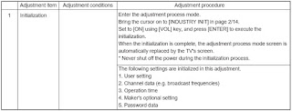
Initialization to factory settings
Caution: When initialization is performed, all user setting data including the channel settings are initialized. Be cautious when making this adjustment.
(The adjustments done in the adjustment process mode are not initialized.)
After the adjustment, cancel the adjustment process mode.
To exit the adjustment process mode, unplug the AC cord from the outlet to make a forced shutdown. (When the power was turned off with the remote controller, once unplug the AC cord and plug it again. In this case, wait 10 seconds or so before plugging.)
Display adjustment procedure
1. Adjusting procedure
Entering the adjustment process mode > COM BIAS adjustment
2. Entering and exiting the adjustment process mode
(1) Before entering the adjustment process mode, press the "TV RESET" button or execute the AV position RESET in the menu video adjustment.
(2) Unplug the AC cord from the outlet to make a forced shutdown.
(3) While holding down the "VOL (+)" and "CH (Ù)" keys at a time, plug the AC cord and turn on the power.
(The "VOL (+)" and "CH (Ù)" keys should be pressed and held until the display appears.)
The letter "K" appears on the screen.
(4) Next, press the "VOL (+)/(–)" or "CH (ù)/(Ù)"key at remote controller.
Multiple lines of red characters appearing on the display indicate that the unit is now in the adjustment process mode.
When you fail to enter the adjustment process mode (the display is the same as normal startup), retry the procedure.
(5) To exit the adjustment process mode after the adjustment is done, unplug the AC cord from the outlet to
make a forced shutdown. (When the power was turned off with the remote controller, once unplug the AC cord and plug it again. In this case, wait 10 seconds or so before plugging.)
Caution: Use due care in handling the information described here lest your users should know how to enter the adjustment process mode. If the settings are tampered in this mode,
unrecoverable system damage may result.
Adjustment process mode key operation table
Lamp error detection
Feature description
This liquid-crystal color TV incorporates a lamp error detection feature (lamp error detection) that automatically turns OFF the power for safety under abnormal lamp or lamp circuit conditions.
If anything is wrong with the lamp or lamp circuit or when the lamp error detection feature is activated for some reason, the following will result.
1 The power of TV main body is turned OFF about six seconds after it is turned ON. (The power LED on
the front of the TV turns red from green and keeps blinking in red (ON for 250ms and OFF for 1sec)).
2 If occurs five times consecutively, it becomes impossible to turn ON the power. (The power LED keeps blinking in red (ON for 250ms and OFF for 1sec)).
Measures
1) Checking with lamp error detection OFF
Enter the display adjustment process mode referring to "11.Display adjustment procedure"
If there is a problem with a lamp or a lamp circuit, the lamp will go out. (The power LED is green.)
Then, you can check the operation to see if the lamp and lamp circuit are abnormal.
2) Resetting the lamp error count
After you have finished checking whether the lamp and lamp circuit are abnormal, reset the lamp error count. If a lamp error is detected five consecutive times, the power cannot be turned on.
Therefore, move to the [L ERR RESET] line, the 4th line on the first page of the "Display process mode", using the "Cursor UP/DOWN" key. Then, reset the [L ERR RESET] value using the "Cursor RIGHT/ LEFT" key. In this case, press the "Cursor UP/DOWN" key to reset it to "0".
[After resetting to "0", perform an operational check to ensure that the lamp error detection feature is not activated.]
List of adjustment process modes (Display)
(Examples)
IC INFORMATIONS
IC3801 (CXA2069Q)
This is a 7-input, 3-output selector. All the video signals but the PC and component lines, coming from the input terminals and tuner, as well as all the audio signals are fed into this IC for being selected.  The video output signal from this IC then flows through the low-pass filter circuits IC401/IC600 (SM5313AS) to the YC separator-incorporating video decoder circuits IC402/IC502 (Main) and IC601 (Sub). The external input audio signal is supplied through IC2701 (Sound Processor) to the digital amplifier circuit.
IC3805 (MM1519XQ)
This is a 4-input, 3-output video selector for component inputs.
The INPUT1 and INPUT3 component inputs and the teletext RGB signals are received. Outgoing are the component/RGB outputs for Main, Sub and Pass.
IC1601 (SDA5550M) (LC-26GA5M/X only)
This is a teletext microprocessor. The teletext data of video signal input is decoded, and the resulting RGB data is put out of this IC.
IC401 (SM5302AS)
The SM5302AS is a 3-channel video buffer that processes the main signal and has a 5th order Butterworth low-pass filter incorporated. The low-pass filter's cut-off frequency can be flexibly preset. This filter puts in and out the video signals from 480i to 1080i.
IC600 (SM5313AS)
The SM5313AS is a 6-channel video buffer that processes the sub signal and has a low-pass filter incorporated.  This IC is able to drive the S video signal, composite signal and component signal, through the 6 channels at once.
IC402 (CXD3802B)
The CXD3802BQ is a digital chroma decoder. The main signal is processed for the luminance signal, color signal and sync signal with respect to the CVBS/YC signal, analog component signal and digital component signal of adaptive 3D comb filter NTSC/PAL system. The output is 10-bit Y/CbCr (ITU_R601).
IC502 (CXD2096Q)
The CXD2096Q is also a digital chroma decoder. The main signal is processed for the luminance signal, chroma signal and sync signal with respect to the adaptive 2D comb filter PAL/NTSC/SECAM system. The output is 10-bit Y/CbCr (ITU_R601).
IC601 (VPC3230D)
The VPC32320D is a digital video decoder. The sub signal is processed for the luminance signal, chroma signal and sync signal with respect to the adaptive 4D comb filter PAL/NTSC/SECAM system. The output is 8- bit Y/CbCr (ITU_R656).
IC802 (IXA835WJ)
The F.P.G.A. (Field Programmable Gate Arrays) chip is designed to get the digitized input signals synchronized and selected accordingly.
IC3300 (IXA091WJ)
This IC is intended to convert the data of video signal, such as I/P conversion and scaling, to adjust the digitized video signals to the output resolution. The output digital signal flows toward IC3201 (LVDS transmitter).
IC3201 (THC63LVD823)
The THC63LVD823 is a 170-MHz LVDS (Low Voltage Differential Signaling) transmitter with 24-bit interface chip selector. This LSI is designed to serialize the RGB, HD, VD, blanking, and pixel clock signals for transmission.
The LVDS (Low Voltage Differential Signaling) system helps convey via cable the high-speed digital signal in the form of differential small-amplitude signal.
The 1LINK consists of 5 pairs of differential signals. The TA, TB, TC and TD pairs are used for data transmission, whereas the TCLK pair for pixel clock transmission. In this way, the TA, TB, TC and TD pairs are sent in 7 data (28 data in total) by a single pixel clock.
The RGB signal (24 bits) and the sync signals (HD, VD, DE), which come into this chip, are arranged in these 28 data.
IC4601 (IXB001WJ)
The input 8-bit RGB signal comes from the dual-linked LVDS chip and the output 8-bit RGB signal goes to the CMOS chip. The sync signals (H, V, DE), in sync with the input signal, become free-run sync signals (H, V, DE).
IC4602 (IXB227WJ)
The EEPROM is designed to store the 10-bit gamma correction and crosstalk correction data. When the set is switched on, the data is read to IC4601 (IXB001WJ).
IC4901 (IXB002WJ)
This is a QS (QuickShot) driver. QS drive is carried out for the input signal from the IC4601 (IXB001WJ) picture quality correction chip. This signal is processed, according to the temperature parameter setting from the monitor microprocessor, to feed out the LVDS signal. FIFO (IC4902: RH-IXA986WJZZQ) is also controlled here for computing.
IC4902 (IXA986WJ)
The 26M bit FIFO chip is a computing memory for the IC4901 (IXB002WJ) QS driver chip.
IC4903 (IXB243WJ)
The EEPROM is designed to store the QS parameters. The data is read frame by frame to the QS driver.
IC4501 (IXB003WJ)
The liquid crystal display panel controller receives the LVDS RGB signal from the QS driver and sends the video signal (RSDS) to the LCD panel.
The control signals for the dimmer and CS circuits are also generated in this IC.
IC4101 (IXA706WJ)
The TFT liquid crystal gradation reference power chip has an 18-line gradation output buffer amplifier, CMOS buffer amplifier and reference voltage supply incorporated.
IC2701 (MSP3450G)
The audio decoder IC serves to decode the S-IF signal and to select the input audio data.
IC2714 (AK4586VQ)
The AK4586 is a 24-bit CODEC with built-in 2CH analog/digital converter and 6CH digital/analog converter.
(The CODEC is a device that converts analog signals to digital bit stream.)
This IC has a 96-kHz/24-bit-compatible DIR (Digital Audio Receiver) incorporated. Also the non-PCM data stream, such as AC-3/MPEG, is automatically detected here.
The CODEC is an electronic circuit that converts audio analog data to digital codes and vice versa. In short, it is a sort of AD and DA converters.
IC2710 (NJU26150)
The NJU26150 is a processor IC that is composed of DIR-incorporating 24-bit DSP (Digital Signal Processor) core and various interfaces. The program written on IC2708 (EEPROM) is downloaded to the built-in PRAM for operation.
The built-in functions include audio delay, BBE, and parametric equalizer. Digital processing is made in the I2S format.
There are 3 data input lines (SDI0, SDI1, SDI2) and 3 data output lines (SDO0, SDO1, SDO2). Two different types of LR clock (LRI, LRO) and BCK (BCKI, BCKO) are used to transfer the data along the serial data line.
IC2700 (NJU26106)
The NJU26106 is a digital signal processor that decodes the matrix-encoded (Lt/Rt) stereo signal. On this set, the processor is used for Dolby Virtual function.
IC1001 (IXB027WJ)
This IC is a high-performance CPLD (Complex Programmable Logic Device). The device serves to communicate with the display and also to control the entire system.
IC2004 (IXA870WJ)
The LCD controller microprocessor has many tasks: OSD control on the LCD monitor, thermistor-sensed panel temperature detection, temperature parameter setting for the QS driver, timing for the liquid crystal display panel controller, dimmer data setting, power control, power line monitoring, remote control decoding, and OPC control.
IC3704 (TA1318AF)
This IC is designed to process the TV component signal synchronization and to measure the frequency.
The frequency measurement function for input signals and other functions for synchronized reproduction are incorporated in a single chip. The chip readily meets the horizontal synchronized reproduction function (15.75 kHz, 31.5 kHz, 33.75 kHz, 45 kHz) and vertical synchronized reproduction function (525I, 525P, 625I, 750P, 1125I, 1125P, PAL 100 Hz, NTSC 120 Hz).


LG 32LK610BPUA, LG 32LK610BBUA LCD TVs – How to upgrade the software, fault checking method

  Software update procedure USB (1) Insert the USB memory Stick to the USB port (2) Automatically detect the SW Version and show the bel...