Saturday, 2 June 2018

LG Optimus 3D Max – Disassembling procedure – How to remove the case – How to Remove the boards – How to replace the LCD


LG Optimus 3D Max 
Tools required : Small philips/crosstip screwdriver
Tiny slotted screwdriver (to tear things apart)
Guitar pick (also to open things and tear them apart)
Remove the 3 screws on the bottom plate and the 8 screws on the upper part, all marked in red.
With the tiny screwdriver go under the bottom plate. Lift the plate and remove it.
Loosen up the frame. Remove it carefully with your hand.
We got to the SIM and SD card board and the motherboard. Start to unpin the relevant cables and pins marked in red.
Remove the SIM and SD card board. You removed the pin next to the SD card tray already and you can see the glue on the board on this picture. Also remove the (whole!) pin between the cameras, circled in red. Remove the pin shown at the bottom of the picture. Remove the board carefully.

Let's remove the motherboard now. Although already pointed out earlier on, the red marked pins are the ones you need to unpin before carefully removing the board. There are four pins marked on the top of the board and three in the lower part. Once you removed them, remove the board.
This is how the board should look, once it is succesfully removed.
Let's continue work at the lower part of the phone. Three things you need to loose or unpin: the sticker that kept the microUSB board in place, the second pin of the cable and the gold foil circled in red.
Now it is a little tricky to tell apart the flex cable that comes from the LCD and needs to be removed and the necessary flex cables that need to be left in place. I tried to mark the gold foil under the two board parts. Where you removed the first bit of gold foil should now be two connectors visible.
Use the guitar pick to detach the glass housing from the housing of the LCD screen. Be careful, you have to detach a lot of pins. Have a close look at the picture before you proceed.
You cannot fully detach the glass because the relevant flex cable has a pin that won't fit through the opening at the top of the phone. Open it carefully like shown in the picture.
This looks a little wild but actually isn't. The LCD sits tight in it's housing. Take the slotted screwdriver to lift it out of it's housing. The LCD is already broken. Anyway, let's stay careful. Because of the flex cable of the LCD it is not yet possible to remove it. Take a sharp small knife or a razor blade to cut those flex cables close to the LCD. Start where the upper red arrow starts and work your way down to the second arrow. Now you can remove the LCD. On the other side you can now identify the old flex cables that you just cut loose. You will have to remove those as well. Take a look at the next steps.
 Start to pull off the gold foil under the cable and don't tear it apart. Go slow! Remove the foil. You will see there is also a light blue foil as shown in the second picture. It's attached to the gold foil. Leave it attached! Once you detached the gold/blue foil, remove the flex cable that lies beneath the black foil that covers the battery compartment. In the first picture I marked red lines show where the flex cable lies. You have to tear it and it won't glue again. Once you removed the flex cable it looks a little bit like a scorpion there :)
Insert the new LCD. Work the flex cable through the designated openings. It's a little messy in the picture, but you will work out how to do it properly.
You worked the flex cable through it's designated opening? Then take the kept gold/blue foil and attach it to the new LCD flex cable like it was attached on the old one. The picture shows how it should like now. You have to fix the cable that goes through the battery compartment. Use duct tape, or, if not available do it like I did: use normal tape. Now you are done. I hope you took notes of how you disassembled the phone. You need to reassemble it now.


Lenovo Thinkpad 13 – Bootable diagnostics program - How to test the battery charge – how to test the backup battery


Lenovo Thinkpad 13
Bootable diagnostic programs
Create a Lenovo Bootable Diagnostics.
To use the diagnostic medium you have created, do one of the following:
If you have created the bootable diagnostic medium on a USB device, do the following:
1. Attach the USB device to the computer.
2. Turn on the computer.
3. When the logo screen is displayed, repeatedly press and release the F12 key. When the Boot Menu window opens, release the F12 key.
4. Use the arrow keys to select USB HDD and then press Enter. The diagnostic program will be launched automatically.
5. Follow the instructions on the screen to use the diagnostic program.
If you have created the bootable diagnostic medium on a CD, do the following:
1. Turn on the computer.
2. Insert the CD into the optical drive.
3. Restart the computer.
4. When the logo screen is displayed, repeatedly press and release the F12 key. When the Boot Menu window opens, release the F12 key.
5. Use the arrow keys to select ATAPI CDx (x: 0, 1, ...) and then press Enter. The diagnostic program will be launched automatically.
6. Follow the instructions on the screen to use the diagnostic program
To verify a power symptom, do the following:
1. Turn off the computer.
2. Connect the ac power adapter.
3. Turn on the computer. If the computer can be turned on, it means that either the battery pack or the ac power adapter is functional.
4. Insert a straightened paper clip into the emergency reset hole to reset the computer. If the computer is still powered on, it means that the ac power adapter is functional.
5. Turn off the computer.
6. Disconnect the ac power adapter and turn on the computer. If the computer can be turned on, it means that the battery pack is functional.
If you suspect a power problem, see the appropriate one of the following power supply checkouts:
“Checking the ac power adapter”
“Checking the built-in battery and operational charging”
“Checking the coin-cell battery”
Checking the ac power adapter.
To check the ac power adapter, do the following:
1. Unplug the ac power adapter cable from the computer.
2. Measure the output voltage at the plug of the ac power adapter cable. See the following illustration:
Note: Output voltage of pin 2 of the ac power adapter might differ from the one you are servicing.
3. If the voltage is not correct, replace the ac power adapter.
4. If the voltage is acceptable, replace the system board.
Note: Noise from the ac power adapter does not always indicate a defect.
Checking the built-in battery and operational charging
Move your pointer to the battery-status icon in the Windows notification area to check the battery status. The battery-status icon displays the percentage of battery power remaining and how long you can use
your computer before you must charge the battery.
To check whether the battery charges properly during operation, do the following:
1. Discharge the battery until the remained battery power is less than 50%.
2. Connect the computer to ac power to charge the battery. If the battery status icon in the Windows notification area indicates that the battery is not charging, remove the battery and let it return to room temperature.
3. Reinstall the battery. If the battery is still not charging, replace the battery pack.
4. Check the battery status icon again. If the same error still exists, replace the system board.
Checking the coin-cell battery
To check the coin-cell battery, do the following:
1. Disconnect the battery connector. See “Disabling the built-in battery”
2. Remove the coin-cell battery.
3. Measure the voltage of the coin-cell battery.
If the voltage is correct, replace the system board.
If the voltage is not correct, replace the coin-cell battery.
If the coin-cell battery discharges quickly after replacement, replace the system board.

HTC Desire X – How replace the touch screen – How to remove the case


Here is the Desire X, with the touch screen damaged, but working.
Once the back cover and battery are removed, its time to dissasembly. First unscrew the 5 torx #5 from back side. Then, with a flat screwdriver, push and open the back cover, from side to side.
Now, on the main board, we have to remove the screw near the camera. Release the connector on the bottom Finally, remove the antenna connector.
Once the bottom connector is loosed, you can take away the sound board and separate the flat cable from underneath. Next, the power button has to be removed. It is a bit sticky, so you may want to use a cutter or knife to separate. Long nails also work.
Now, its time to release the vibrator connector (or vibrator from holder - easier), and then release the lower connector on the main board ( see pic 2). Remove the black tape first, and then use some tweezers to pull out the connector. Once its done, lift by one side the main board, and you can see the LCD connector. Open the white tab by lifting it up at the edge, and remove the flat cable.
Now, its time to remove the product label, and keep it without bend to put back together. Then, under the silver ribbon, which is hard to remove, there is another flat connector, which must be disconnected.
The flat cable that goes to main board must be removed, and the flat cable of the touch is loosed. Remove the speaker from the top side of the phone.
To remove the glue from the LCD and touch of the screen, we have to heat all the screen, with special attention to the top and bottom zones. I have one Hot Air Station, but you can do it with a hairdryer. With more time you heat, more easy to remove, but be careful... With a Metal thin blade, insert between bezel and LCD, and bend it to start releasing.
Finally, the both parts comes apart. At the left, the LCD + touch. At the right, the chassis. Now, to assembly the unit back together, follow the steps backwards.

Motorola Slvr L7 – Disassembling procedure – How to replace the Key board


Motorola Slvr L7:  DISASSEMBLING PROCEDURE 
Push down on the black tab located at the top center of the Motorola phone
Remove the battery by pulling the battery from the top center
Remove the four (4) T6 Torx screws from the rear metal plate.
Insert the flat end of a spudger and pry the metal cover up off the phone
Carefully, disconnect the two connectors from their sockets on the motherboard using the flat end of a spudger.
Use a spudger to pry the antenna cable connectors from its respective socket on the motherboard. De-route the antenna cable by pulling it out.
Starting at one side, use a spudger to lift and remove the black plastic screw cover at the bottom of the phone near the speaker The cover is attached by several clips, so some force may be required, especially to unclip the first clip. Be careful not to loose the round plastic piece that covers the microphone.
Remove the 2 newly exposed T6 screws
Starting at the top, insert the flat end of a spudger and pry the frame of the phone. The frame is attached by several clips, so some force may be required to dislodge the first clip. Work your tool around the entire edge of the phone, moving as soon as you hear a clip come undone, to avoid breaking the frame.
Carefully, Insert the flat end of a spudger and pry the keyboard up off the phone.

Lenovo B550 – Disassembling procedure – How to remove the battery – How to test the charger – How to check the battery pack


To verify a symptom, follow the steps below:
1. Turn off the computer.
2. Remove the battery pack.
3. Connect the AC adapter.
4. Make sure that power is supplied when you turn on the computer.
5. Turn off the computer.
6. Disconnect the AC adapter and install the charged battery pack.
7. Make sure that the battery pack supplies power when you turn on the computer.
If you suspect a power problem, see the appropriate one of the following power
supply checkouts:
“Checking the AC adapter ”
“Checking operational charging”
“Checking the battery pack ”
Checking the AC adapter
You are here because the computer fails only when the AC adapter is used.
If the power-on indicator does not turn on, check the power cord of the AC adapter for correct continuity and installation.
To check the AC adapter, follow the steps below:
1. Unplug the AC adapter cable from the computer.
2. Measure the output voltage at the plug of the AC adapter cable. See the following figure:
Note: Output voltage for the AC adapter pin No. 2 may differ from the one you are servicing.
3. If the voltage is not correct, replace the AC adapter.
4. If the voltage is acceptable, do the following:
Replace the system board.
Note: Noise from the AC adapter does not always indicate a defect.
Checking operational charging
To check whether the battery charges properly during operation, use a discharged battery pack or a battery pack that has less than 50% of the total power remaining when installed in the computer.
Perform operational charging. If the battery status indicator or icon does not light on, remove the battery pack and let it return to room temperature. Reinstall the battery pack. If the charge indicator or icon is still off, replace the battery pack.
If the charge indicator still does not light on, replace the system board. Then reinstall the battery pack. If it is still not charged, go to the next section.
Checking the battery pack
Battery charging does not start until the Power Meter shows that less than 95% of the total power remains; under this condition the battery pack can charge to 100% of its capacity. This protects the battery pack from being overcharged or from having a shortened life.
To check your battery, move your cursor to the Power Meter icon in the icon tray of the Windows taskbar and wait for a moment (but do not click it), and the percentage of battery power remaining is displayed. To get detailed information about the battery, double-click the Power Meter icon.
Note: If the battery pack becomes hot, it may not be able to be charged.
Remove it from the computer and leave it at room temperature for a while. After it cools down, reinstall and recharge it.
To check the battery pack, follow the steps below:
1. Turn off the computer.
2. Remove the battery pack and measure the voltage between battery terminals 1 (+) and 7 (-). See the following figure:
3. If the voltage is less than +11.0 V DC, the battery pack has been discharged.
Note: Recharging will be continued for at least 3 hours, even though the indicator does not light on. If the voltage is still less than +11.0 V DC after recharging, replace the battery.
4. If the voltage is more than +11.0 V DC, measure the resistance between battery terminals 5 and 7. The resistance must be 4 to 30 KΩ.
If the resistance is not correct, replace the battery pack. If the resistance is correct, replace the system board.
Restore of factory default
The Lenovo B550 computers come with pre-installed OneKey Rescue System. In order to save application files and the initial backed up files of the system, the hard disk in a Lenovo computer includes a hidden partition when it is shipped. If you need to restore the system to the point of your first boot up, just enter Lenovo OneKey Rescue System and run Restore to factory default.
DISASSEMBLING PROCEDURE 
Battery pack
Unlock the battery release lever 1. Holding the battery release lever in the unlocked position 2, remove the battery pack in the direction shown by arrow 
3.Hard disk drive (HDD) slot cover and HDD
Loosen the screws , but do not remove them. Remove the HDD slot cover in the direction shown by arrow .

Friday, 1 June 2018

How to replace the wirefuse, control board, steam switch and Jaw - Nespresso EF748, Nespresso EF749 – Coffee machine


General disassembly (stage 1)
Tools:
- Special screwdriver (oval)
General information:
The screws are labelled with letters (A, B and C) in the figures.
These refer to the tightening torques for the screws.
A = 0,5 to 0,9 Nm
B = 0,8 to 1,4 Nm
C = 1,3 to 1,8 Nm
A and B can be tightened by hand (A = tighten lightly, B = tighten firmly).
For tightening screws labelled C it is imperative that a torque wrench is used.
Procedure:
1. Remove water tank, drip tray, and capsule container.
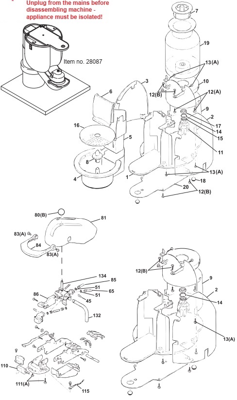
2. Place machine on the disassembly jig (item no. 28087).
3. Remove screws (13) on the underside and rear of the side pieces.
4. Remove side pieces (2 and 3).
General disassembly (stage 2)
Tools
- Torx screwdriver T10, T15
- Special screwdriver (oval)
Procedure
1. General disassembly stage 1.
2. Remove 3 bolts (13) on the cover at the rear (9) on the underside.
3. Open jaw and remove screws (111) on the cover.
4. Unscrew ball (80) on the jaw stick.
5. Remove screws (83) and closing lever (84).
6. Move cover (81) a little to the side and remove.
7. Remove 2 bolts (12) on the cover at the rear on the top.
8. Remove cover at the rear (9).
Replacing fine-wire fuse
Tools:
- Torx screwdriver T15
- Long-nose pliers
- Torque wrench
Procedure:
1. General disassembly stage 1 and 2.
2. Remove all connections with red cable.
3. Undo clamp (43).
4. Replace fault fine-wire fuse (998).
5. Assemble in reverse sequence. Tighten bolt (46) to torque C using torque wrench

Replacing control board
Tools:
- Torx screwdriver T10
- Long-nose pliers
General disassembly stage 1
2. Place earthing strap around the wrist and
connect to the earthing cable on the unplugged machine! In this way a potential
difference is avoided.
3. Remove connections from the board.
4. Undo 2 screws (12) and remove the
control board.
5. Replace control board (59).
6. Assemble in reverse sequence.
Replacing main switch or steam switch
Tools:
- Torx screwdriver T10
- Long-nose pliers
Procedure:
1. General disassembly stage 1
2. Remove screws (12) on underside of appliance.
3. Remove connections
4. Replace main switch (62) or steam switch (63).
5. Assemble in reverse sequence.
Replacing LED
Tools:
- Torx screwdriver T10
Procedure:
1. General disassembly stage 1
2. Remove connector in the electronic mainboard.
3. Remove screws (12) and cover (33).
4. Remove screw (48) on the LED board.
5. Replace LED board (58).
6. Assemble in reverse sequence.
Replacing steam pipe
Tools:
- Torx screwdriver T10
- Torque wrench
Procedure:
1. General disassembly stage 1
2. Remove screws (12).
3. Remove cover (32).
4. Remove steam pipe (40) and replace.
5. Assemble in reverse sequence. Tighten bolt (12) to torque C using torque wrench.
Replacing the jaw
Tools:
- Torx screwdriver T10, T15
- Cross-headed screwdriver
- Long-nose pliers
Procedure:
1. General disassembly stage 1
2. Open jaw and remove screws (111) on the cover.
3. Unscrew ball (80) on the jaw stick (134).
4. Remove screws (83) and closing lever (84).
5. Move cover (81) a little to the side and remove.
6. Disassemble hoses (85, 65) on the ceramic valve and remove grounding wire (115) on the support.
7. Pull off hose (132) on the expansion housing.
8. Unplug heating PTC (110) and reed contact (86) on the control board.
9. Remove screws (131) on the support module (126).
10. Remove complete jaw and replace
Complete jaw disassembly
Tools:
- Hammer (plastic head)
- Drift No. 4
- Torx screwdriver T10
- Torque wrench
Procedure:
1. General disassembly stage 1.
2. Disassemble jaw as per page 27.
3. Remove capsule cage (see page 31)
4. Remove cover (112).
5. Remove springs (98).
6. Remove shafts (108 +127).
7. Remove side closing lever (120), locking lever (119) and shaft (113).
8. Remove screws on the control board.
9. Remove swivelling plate (97) with ejector lever (94) and spring bearing (99).
Replacing reed contact
Perform points 1 to 9
10.Remove screws (87).
11.Remove screws (96) and bearing (109).
12.Remove reed contact (86) and replace.
Attention: The cover on the ceramic valve must not be removed.
13.Assemble in reverse sequence.
Replacing connection to capsule cage
Perform points 1 to 9
10.Remove screws (96) and bearing (109).
11.Remove clamp (45).
12.Replace connection (91) and fit new seal (90).
13.Assemble in reverse sequence.
Replacing ceramic valve
Perform points 1 to 9
10.Remove screws (96) and bearing (109).
11.Remove clamp (45) on the ceramic valve.
12.Remove connection (91) and hose (88).
13.Remove screws (87) on the ceramic valve.
14.Replace complete ceramic valve (incl. reed contact, 86).
15.Assemble in reverse sequence. Fit new seal (90) and tighten screws (87) to torque C using torque wrench.

Nespresso EF748, Nespresso EF749 – Coffee Machine - How to replace the pump and thermoblock


General disassembly (stage 1)
Tools:
- Special screwdriver (oval)
General information:
The screws are labelled with letters (A, B and C) in the figures.
These refer to the tightening torques for the screws.
A = 0,5 to 0,9 Nm
B = 0,8 to 1,4 Nm
C = 1,3 to 1,8 Nm
A and B can be tightened by hand (A = tighten lightly, B = tighten firmly).
For tightening screws labelled C it is imperative that a torque wrench is used.
Procedure:
1. Remove water tank, drip tray, and capsule container.
2. Place machine on the disassembly jig (item no. 28087).
3. Remove screws (13) on the underside and rear of the side pieces.
4. Remove side pieces (2 and 3).
General disassembly (stage 2)
Tools
- Torx screwdriver T10, T15
- Special screwdriver (oval)
Procedure
1. General disassembly stage 1.
2. Remove 3 bolts (13) on the cover at the rear (9) on the underside.
3. Open jaw and remove screws (111) on the cover.
4. Unscrew ball (80) on the jaw stick.
5. Remove screws (83) and closing lever (84).
6. Move cover (81) a little to the side and remove.
7. Remove 2 bolts (12) on the cover at the rear on the top.
8. Remove cover at the rear (9).
Replacing thermoblock
Tools / aids:
- Torx screwdriver T10, T15
- Flat nose pliers
- Open-ended spanner 8/10mm AF
- Pot to collect water
- Torque wrench
Procedure:
2. Remove bolt (47) on the thermoblock (66).
3. Remove all electrical connectors.
4. Remove fine-wire fuse clip (43).
5. Remove NTC temperature sensor (64).
ATTENTION: Keep a pot at hand for collecting the water left in the thermoblock.
6. Remove water connections on the thermoblock.
7. Replace thermoblock (66).
8. Assemble in reverse sequence. Only tighten NTC temperature sensor lightly until the spring washer is flat. Tighten bolt (46) to torque C using torque wrench.
Replacing NTC
Tools:
- Open-ended spanner 10mm AF
Procedure:
1. Remove connector on the logic board
2. Undo NTC temperature sensor (64) replace
3. Assemble in reverse sequence. Only tighten NTC temperature sensor lightly until the spring washer is flat.
Replacing pump
Tools / aids:
- Torx screwdriver T10
- Open-ended spanner 14mm AF
- Long-nose pliers
- Pot to collect water
Procedure:
1. General disassembly stage 1
2. Remove all electrical connections
3. Remove steam switch (30, 63) on the underside of the appliance to make it easier to disassemble the pump

4. Remove clamp (45) and hose (65).
ATTENTION: Keep a pot at hand for collecting the water left in the pump.
5. Remove angled hose (57).
6. Release pump first from bottom rubber strap, then from the top rubber strap (54).
7. Remove seal (51) and angle (37).
8. Replace pump (61).
9. Insert seal (51) and tighten corner connector (37).
10.Turn corner connector to the correct position using open-ended spanner on pump projection.
11.Remaining assembly in reverse sequence.

LG 32LK610BPUA, LG 32LK610BBUA LCD TVs – How to upgrade the software, fault checking method

  Software update procedure USB (1) Insert the USB memory Stick to the USB port (2) Automatically detect the SW Version and show the bel...