Magnetron check, High voltage rectifier check, High voltage capacitor check, High voltage rectifier check and more..

REMEMBER
TO CHECK 3D
1) Disconnect the supply.
2) Door opened, and wedged open.
3) Discharge high voltage capacitor.
1) Disconnect the supply.
2) Door opened, and wedged open.
3) Discharge high voltage capacitor.
WARNING AGAINST THE CHARGE OF THE HIGH VOLTAGE CAPACITOR
The high-voltage capacitor remains charged about 60 seconds after the oven has been switched off.
Wait for 60 seconds and then short-circuit the connection of the high-voltage capacitor (that is, of the connecting lead of the high-voltage rectifier) against the chassis with the use of an insulated screwdriver.
If the oven becomes inoperative Because of a blown fuse F2 (F8A) in the monitored latch switch SW1 – monitor switch SW3 circuit, check the monitored latch switch SW1 and monitor switch SW3 before replacing the fuse F2 (F8A).
MAGNETRON TEST
CARRY OUT 3D CHECK
Isolate the magnetron from high voltage circuit by removing all leads connected to the filament terminal.
To test for an open circuit filament use an ohmmeter to make a continuity test between the magnetron filament terminals, the meter should show a reading of less than 1 ohm.
To test for a short circuit filament to anode condition, connect ohmmeter between one of the filament terminals and the case of the magnetron (ground). This test should be indicated an infinite resistance. If a low or zero resistance reading is obtained then the magnetron should be replaced.
MICROWAVE
OUTPUT POWER (IEC-60705-1988)
The following test procedure should be carried out with the microwave oven in a fully assembled condition (outer case fitted). Microwave output power from the magnetron can be measured by way of IEC 60705, i.e. it is measured by how much power the water load can absorb. To measure the microwave output power in the microwave oven, the relation of calorie and watt is used. When P(W) heating works for t(second), approximately P x t/4.187 calorie is generated. On the other hand, if the temperature of the water with V(ml) rises ΔT (°C) during this microwave heating period, the calorie of the water is V x ΔT.
The following test procedure should be carried out with the microwave oven in a fully assembled condition (outer case fitted). Microwave output power from the magnetron can be measured by way of IEC 60705, i.e. it is measured by how much power the water load can absorb. To measure the microwave output power in the microwave oven, the relation of calorie and watt is used. When P(W) heating works for t(second), approximately P x t/4.187 calorie is generated. On the other hand, if the temperature of the water with V(ml) rises ΔT (°C) during this microwave heating period, the calorie of the water is V x ΔT.
The formula is as follows;
P x t / 4.187 = V x Δ T+0.55 x mc (T2-T0)
Our condition for water load is as follows:
Room temperature.....................around 20°C
Water load..........................................1000 g
Heating time........................................47 sec.
T2......................................Final Temperature
P (W) = 4.187 x V x ΔT / t
Power supply Voltage........Rated voltage
Initial temperature(T1).............10 ± 1°C
Mass of container (mc)....................330 g
P = 90 x ΔT + 0.55 x mc (T2-T0)/47
Measuring
condition
1. Container
The water container must be a cylindrical borosilicate glass vessel having a maximum material thickness of 3 mm and an outside diameter of approximately 190 mm.
2. Temperature of the oven and vessel.
The oven and the empty vessel are at ambient temperature prior to the start of the test.
3. Temperature of the water The initial temperature of the water is (10 ± 2)°C.
4. Select the initial and final water temperature so that the maximum difference between the final water temperature and the ambient temperature is 5K.
5. Select stirring devices and measuring instruments in order to minimize addition or
removal of heat.
6. The graduation of the thermometer must be scaled by 0.1°C at minimum and an accurate thermometer.
7. The water load must be (1000 ± 5) g.
8. “t” is measured while the microwave generator is operating at full power. Magnetron filament heat-up time is not included.
NOTE: The operation time of the microwave ovens is “t + 3” sec. (3 sec. is magnetron filament heat-up time.)
Measuring method
1. Measure the initial temperature of the water before the water is added to the vessel. (Example: The initial temperature T1 = 11°C)
2. Add the 1 litre water to the vessel.
3. Place the load on the centre of the shelf.
4. Operate the microwave oven at HIGH for the temperature of the water rises by a value ΔT of (10 ± 2) K.
5. Stir the water to equalize temperature throughout the vessel.
6. Measure the final water temperature. (Example: The final temperature T2 = 21°C)
7. Calculate the microwave power output P in watts from above formula.
Room
temperature ................T0 = 21°C Initial temperature............. T1 =
11°C
Temperature after (47+ 3) = 50 sec................................................... T2 = 21°C
Temperature difference Cold-Warm.................................................ΔT1 = 10°C
Measured output power
The equation is “P = 90 x ΔT” .................................. P = 90 x 10°C = 900Watts
Temperature after (47+ 3) = 50 sec................................................... T2 = 21°C
Temperature difference Cold-Warm.................................................ΔT1 = 10°C
Measured output power
The equation is “P = 90 x ΔT” .................................. P = 90 x 10°C = 900Watts
The measured output power should be at least ± 15 % of the rated output power.
CAUTION: 1°C CORRESPONDS TO 90 WATTS. REPEAT MEASUREMENT IF THE POWER IS INSUFFICIENT
HIGH VOLTAGE TRANSFORMER TEST
High voltages and large currents are present at the secondary winding and filament winding of the high voltage transformer. It is very dangerous to work near this part when the oven is on. NEVER make any voltage measurements of the high-voltage circuits, including the magnetron filament.
Disconnect the leads to the primary winding of the power transformer.
Disconnect the filament and secondary winding connections from the rest of the HV circuitry. Using an ohmmeter, set on a low range, it is possible to check the continuity of all three windings. The following readings should be obtained:-
a. Primary winding ............................approximately 2 Ω
b. Secondary winding ....................approximately 127 Ω
c. Filament winding ..................................less than 1 Ω
If the reading obtained are not as stated above, then the power transformer is probably faulty and should be replaced.
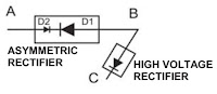
HIGH VOLTAGE RECTIFIER TEST
Isolate the high voltage rectifier assembly from the HV circuit. The high voltage rectifier can be tested using an ohmmeter set to its highest range. Connect the
ohmmeter across the terminal B+C of the high voltage rectifier and note the reading obtained. Reverse the meter leads and note this second reading.
The normal resistance is infinite in one direction and more than 100 kΩ in the other direction
Isolate the high voltage rectifier assembly from the HV circuit. The asymmetric rectifier can be tested using an ohmmeter set to its highest range across the terminals A+B of the asymmetric rectifier and note the reading obtained.
Reverse the meter leads and note this second reading. If an open circuit is indicated in both direction then the asymmetric rectifier is good. If an asymmetric rectifier is shorted in either direction, then the asymmetric rectifier is probably faulty and must be replaced with high voltage asymmetric rectifier.
When the asymmetric rectifier is defective, check whether magnetron, high voltage rectifier, high voltage wire or filament winding of the high voltage transformer is shorted.

FOR MEASUREMENT OF THE RESISTANCE OF THE RECTIFIER, THE BATTERIES OF THE MEASURING INSTRUMENT MUST HAVE A VOLTAGE OF AT LEAST 6 VOLTS, BECAUSE OTHERWISE AN INFINITE RESISTANCE MIGHT BE SHOWN IN BOTH DIRECTIONS
HIGH
VOLTAGE CAPACITOR TEST
A. Isolate
the high voltage capacitor from the circuit.
B. Continuity check must be carried out with measuring instrument which is set to the highest resistance range.
C. A normal capacitor shows continuity for a short time (kick) and then a resistance of about 10 MΩ after it has been charged.
D. A short-circuited capacitor shows continuity all the time.
E. An open capacitor constantly shows a resistance about 10 MΩ because of its internal 10 MΩ resistance.
F. When the internal wire is opened in the high voltage capacitor, the capacitor shows an infinite resistance.
G. The resistance across all the terminals and the chassis must be infinite when the capacitor is normal.
If incorrect readings are obtained, the high voltage capacitor must be replaced.
HIGH VOLTAGE TRANSFORMER REMOVAL
1. CARRY OUT 3D CHECKS
2. Disconnect the main wire harness from the high voltage transformer.
3. Disconnect the filament leads and high voltage wire of high voltage transformer from high voltage capacitor and the magnetron.
Remove the two (2) screws and one (1) washer holding the transformer to the base plate.
5. Remove the transformer.
6. Now the high voltage transformer is free.
The line voltage is supplied to the primary winding of the high voltage transformer. The voltage is converted to about 3.3 volts A.C. output on the filament winding and high voltage of approximately 2000 volts A.C. on the secondary winding.
2. The filament winding voltage (3.3 volts) heats the magnetron filament and the high voltage (2000 volts) is sent to the voltage doubling circuit, where it is doubled to negative voltage of approximately 4000 volts D.C..
3. The 2450 MHz microwave energy produced in the magnetron generates a wavelength of 12.24 cm. This energy is channeled through the waveguide (transport channel) into the oven cavity, where the food is placed to be cooked.
4. When the cooking time is up, a single tone is heard and the relays RY1 + RY3 + RY6 go back to their home position. The circuits to the oven lamp, high voltage transformer, fan motor and turntable motor are cut off.
MAGNETRON
REMOVAL
Disconnect
the H.V. wire B (part of H.V. transformer) and filament lead of the transformer
from the magnetron.
3. Carefully remove three (3) screws holding the magnetron to the waveguide, when removing the screws hold the magnetron to prevent it from falling.
4. Remove the one (1) screw holding the magnetron to the chassis support.
3. Carefully remove three (3) screws holding the magnetron to the waveguide, when removing the screws hold the magnetron to prevent it from falling.
4. Remove the one (1) screw holding the magnetron to the chassis support.
5.
Remove the magnetron from the waveguide with care so the magnetron antenna is
not hit by any metal object around the antenna.
6. Now, the magnetron is free.
6. Now, the magnetron is free.
WHEN REPLACING THE
MAGNETRON, BE SURE THE R.F. GASKET IS IN PLACE AND THE MAGNETRON MOUNTING
SCREWS ARE TIGHTENED SECURELY

