Wednesday, 29 May 2019

HP 17 Notebook – Disassembling procedure

How to remove the battery - How to remove the display unit -  HP 17 Notebook – Disassembling procedure

Disassembling procedure 
How to remove Battery
Before removing the battery, follow these steps:
1. Shut down the computer. If you are unsure whether the computer is off or in Hibernation, turn the computer on, and then shut it down through the operating system.
2. Disconnect all external devices connected to the computer.
3. Disconnect the power from the computer by first unplugging the power cord from the AC outlet and then unplugging the AC adapter from the computer.
Remove the battery:
1. Turn the computer upside down on a flat surface.
2. With the battery bay toward you, slide the battery lock latch (1) to unlock the battery and then slide the battery release latch (2) to release the battery.
3. Pivot the battery (3) upward and then remove it from the computer (4).
How to remove Optical drive
Before removing the optical drive, follow these steps:
1. Shut down the computer. If you are unsure whether the computer is off or in Hibernation, turn the computer on, and then shut it down through the operating system.
2. Disconnect all external devices connected to the computer.
3. Disconnect the power from the computer by first unplugging the power cord from the AC outlet and then unplugging the AC adapter from the computer.
4. Remove the battery
Remove the optical drive:
1. Remove the screw (1) that secures the optical drive to the computer.
2. Use a flat tool to press on the optical drive bracket tab (2) to release the optical drive.
3. Remove the optical drive from the computer.
How to remove Base enclosure
Before disassembling the computer, follow these steps:
1. Shut down the computer. If you are unsure whether the computer is off or in Hibernation, turn the computer on, and then shut it down through the operating system.
2. Disconnect all external devices connected to the computer.
3. Disconnect the power from the computer by first unplugging the power cord from the AC outlet and then unplugging the AC adapter from the computer.
4. Remove the battery
5. Remove the optical drive
Remove the base enclosure:
1. Turn the computer face down, and remove the rubber feet (1), the two screws (2) and lift the end caps (3).
2. Remove the ten Phillips screws.
3. Remove five screws (1) around the battery area, three broadhead screws (2) in the optical drive bay and one screw (3) near the display hinge.
4. Turn the computer right side up and carefully remove the top cover.
5. Carefully disconnect the following cables:
Power button cable (1)
Keyboard cable (2)
TouchPad cable (3)
Lift the top cover (4) to remove it from the computer.
How to remove Display panel
Before removing the display panel, follow these steps:
1. Shut down the computer. If you are unsure whether the computer is off or in Hibernation, turn the computer on, and then shut it down through the operating system.
2. Disconnect all external devices connected to the computer.
3. Disconnect the power from the computer by first unplugging the power cord from the AC outlet and then unplugging the AC adapter from the computer.
4. Remove the battery
5. Remove the optical drive
6. Remove the top cover from the base enclosure
Remove the display panel:
1. Open the computer.
2. Disengage the display cable (1) and disconnect the display connector (2) on the left side base of the display panel.
3. On the right side, disconnect the WLAN cable (3) and carefully remove the cable from the retaining tabs (4).
4. Remove the power connector cover by removing the two Phillips screws (1) and lifting the cover (2).
5. Remove the six Phillips screws (1) on the left and one broadhead screw (2) on the right side base of the display panel. Lift the panel up (3).
6. Open the panel cover (1), swivel the display panel hinges (2) on both sides and then tilt up the display panel hinge (3) to release it.
7. Loosen the edges of the back cover (1), (2), and (3) from all four sides of the display bezel and lift the display panel (4).
8. To remove the panel, remove the four Phillips screws (1) and any adhesive that secures the display panel to the back cover and lift the display panel (2) carefully.
9. If it is necessary to remove the display panel cable or access the webcamera and microphone, follow these steps. With the display bezel upside down, disconnect the webcamera/microphone connectors (1) and from the routing channel built into the back cover.
Carefully release the cable from the channel guides, the guides in the display hinge, and remove the display panel cable (2). Lift the cable to remove it.
10. On select models, removing the panel also requires disengaging the panel from the back cover latch. To disconnect the display panel, carefully rotate the display panel (1) to open it. Push upward on the connection latch (2)panel and then disengage the panel from the back cover (3)

Monday, 13 May 2019

Rolsen RL-26B01- how to enter the service mode, adjustments - Chassis MST9E19


Many electrical and mechanical parts in the chassis have special safety-related characteristics. These characteristics are often passed unnoticed by a visual inspection. When replacement parts are required, be sure the service technician uses replacement parts specified by us that have the same characteristics as the original part. Unauthorized substitutions may result in fire, electric shock and injury to persons or other hazards. This LCD TV product should be situated away from heat source such as radiation, stoves, or other product that produce heat.
This Panel is a TFT LCD module supports 1366 x 768 WXGA format and can display true 16.7M colors (8-bit colors).
Service Mode and Adjustment

Method-1 Use the remote control, first open MAIN MENU with MENU button, and choose PICTURE with the CHANNEL UP/DOWN button, then choose the Brightness with VOLUME UP, while Brightness value is 50, press 0,5,3,2. You can enter factory menu.
Method-2 Use the remote control, first open MAIN MENU with MENU button, and choose SOUND with the CHANNEL UP/DOWN button, then choose the Balance with VOLUME UP, while Balance value is 0, press 0,5,3,2. You can enter factory menu.
Factory Menu
White Balance
Auto Test
Auto Calibration
LOGO
OSD Language
Country
Option
Factory Init
Test Pattern
Version:
White Balance
R DRV 10
G DRV 10
B DRV 10
R CUT 128
G CUT 128
B CUT 128
BRIGHT_H 80
CONTRAST _H 80
BRIGHT_L 40
CONTRAST_L 40
Auto Calibration
Auto Color
Color Temp. Standard
RED COLOR 128
GREEN COLOR 128
BLUE COLOR 128
LOGO
NULL
HISENSE
WELCOME
Option
SOURCE
TV
BRIGHT 0
10
BRIGHT 50
100
BRIGHT 100
135
CONTRAST 0
60
CONTRAST 50
125
CONTRAST 100 155
TOFAC
M
HDMI Cable
Standard
Factory Initialization
QingDao
HuangDao
Guiyang
Hungary
France
Austria
CLEAR PROTECTLY
CLEAR UNPROTECTLY
Design Menu
Picture Mode
Sound Mode
Sound Settings
Power Save
PIP Option
EMI
MOVESHARPNESS
LipSync
Picture Mode
Standard
Brightness
50
Contrast
50
Colour
50
Bright
Brightness
60
Contrast
60
Colour
55
Soft
Brightness
45
Contrast
45
Colour
45
Sound Mode
Standard
120Hz
12
500Hz
10
1.5KHz
11
5KHz
8
10KHz
15
Music
120Hz
19
500Hz
11
1.5KHz
12
5KHz
14
10KHz
20
Speech
120Hz
4
500Hz
10
1.5KHz
12
5KHz
7
10KHz
5
Sound Settings
VOLUME 0 128
VOLUME 1 79
VOLUME 20 36
VOLUME 40 31
VOLUME 100 17
TVPRE SCALER 2
VOLUME SCALER 0

Thursday, 9 May 2019

DLM32C1 SL-223M chassis - Daewoo LCD TV Service mode, connector voltages, Power board circuit diagram


Daewoo DLM-26C2, DLM-26C3, DLM-32C1D, DLM-32C2, DLM-32C3, DLM-37C3, DLM-42C1
PAL, PAL-M, PAL-N,  NTSC, NTSC4.43,  SECAM
Entering SERVICE MODE
Using the Service Remote controller, you can enter service mode directly.
Adjustment REMOCON and EEPROM initial DATA
A. The adjustment Specification use the SERVICE REMOCON R-34SVC
(S/N: 48B3034SVC)
B. Adjustment DATA
Description of SERVICE MODE ITEM
A. S1(1) : Heat-Run Key
B. S2(2) : Gumi Channel Map Write
C. S3(3) : Volume Test
=> This key can check sound
D. S4(4) : EDIE WRITE
=> Using this key, you can update EDID data.
E. S5(5) : PANEL TEST
=> Using this key, you can test problem of PANEL, as confirm white pattern, red pattern, blue pattern, green pattern.
F. S6(6) : PICTURE TEST
=> Using this key, you can test brightness, contrast and color.
G. S7(7) : DEMPOL CHANNEL MAP WRITE
H. S8(8) : EEPROM Erase and White Balance adjustment
=> Using this key, you can erase EEPROM data and adjust White balance.
I. S9(9) : Device control
=> This key only use for R&D.
J. S10(10) : Option key
=> Using this key, you can adjust SSC, Dimming, Panel Type, Control key and etc.
K. S11(11) : I2C STOP key
=> This key only use for R&D.
L. S12(SLEEP) : Shipping key
=> Using this key, you can set up at shipping mode.
To adjust WHITE BALANCE, refer to below process.
6-1. Insert white pattern to component input Signal Generator : 802BT (By Quantum Data)
Resolution : 1280x720p @60Hz,
Pattern : Grey Scale (11 step)
6-2. Confirm ‘dimming’ in service mode (=s10) 32C3 = 0, 26C3 = 255
6-3. Attach white balance meter(CA-210) on center of Panel
6-4. Press the service key s8
6-5. Adjust white balance with valiable R.G.B cutoff / drive.
Color coordinates
X = 0.280 0.01, Y = 0.285
X = 0.280 0.01, Y = 0.290
0.01, cd/m2 = 50cd/m2
0.01, cd/m2 = 300cd/m2
6-6. Press s8 buttorn to escape SERVICE MODE
The difference of LCD Panel is not so much, therefore we don’t adjust white balance.
POWER PCB voltages
Other connector voltages
Power board [SMPS] schematic 
Service mode
Typical Symptoms of PCBs problem or bad connection
A. Symptom of initial latch up
- Define initial latch up : When turn on the power, both LEDs light up red and TV is not working.
- Repairing method : This is typical symptom when ROM(ICU3) is incorrectly connected at socket. So if you find this symptom, you must try to that ROM(ICU3) and socket have correct contact.
- As this method, TV set is not repaired, replace MAIN PCB.
B. Symptom of No image when LED and Back Light are working.
- Define No image : LED and BACK LIGHT of panel are correctly working but any image does not display.
- Repairing method : This is typical symptom when LVDS cable incorrectly connects.
So if you find this symptom, check LVDS connection.
- As this method, TV set is not repaired, replace Main or Sub PCB.
C. Representative Symptom caused by bad Connection between PCBs
=> Note: Dust or extraneous material may cause bad connections. Most of the time, applying soft brush, AIR FRESHIER, or breath to clean dust or extraneous materials can solve it. And then reassemble the Connector.

Monday, 22 April 2019

Lenovo YOGA Tablet 2-851F – Ac adapter test procedure – How to remove the case – How to check battery status


Lenovo YOGA Tablet 2-851F 
To verify a symptom, follow the steps below:
1. Turn off the computer.
2. Remove the battery pack.
3. Connect the AC adapter.
4. Make sure that power is supplied when you turn on the computer.
5. Turn off the computer.
6. Disconnect the AC adapter and install the charged battery pack.
7. Make sure that the battery pack supplies power when you turn on the computer.
If you suspect a power problem, see the appropriate one of the following power supply checkouts:
“Checking the Computer AC Charger”
“Checking the internal battery status”
Checking the Computer AC Charger
When you use the computer AC Charger to charge the tablet but no power is charged, see the instructions in this topic to check the computer AC Charger.
To check the computer AC Charger, do the following:
1. Disconnect the micro-USB cable from the tablet.
2. Measure the output voltage across the connector marked B of the micro-USB cable. Refer to the following figure:
Note: The output voltage across pin 3 of the micro-B connector might be different from the one you are servicing.
3. If the voltage is not correct, replace the micro-USB cable.
4. If the voltage is acceptable, replace the system board.
Checking the internal battery status
To check the battery status of the tablet, do either of the following:
Approximate information about the battery status
Get the approximate status of the battery at any time by checking the battery status icon on the system bar in the upper-right corner of the screen. The shorter the green bar is, the less the battery power remains.
Accurate information about the battery status
To get the accurate information about the battery status of the tablet, do the following:
1. Open the Android Settings screen.
To open the Android Settings screen, do either of the following:
From the main Home screen, touch the Android Settings icon on
Lenovo Launch Zone. The Android Settings screen is displayed.
Pull down the application icon from the action bar and then touch Settings. The Android Settings screen is displayed.
2. Touch Battery in the Device section on the Android Settings screen.
3. The accurate percentage of the remaining battery power is shown on the screen.
Disassembling procedure 
How to remove Rear cover
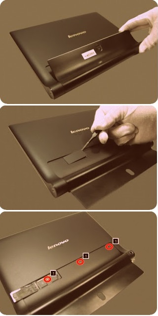
1. Open the hinge frame.
2. Open the card slot cover using a thin flat blade or guitar pick.
3. Remove screws 1 on the rear cover as shown in the figure below.
4. Separate the bottom right corner of the rear cover from the main body of the tablet using a suction tool as shown in the figure below.
5. Hold the tablet in one hand and use a guitar pick to unlock the rear cover from the tablet along the joint line as shown in the figure below.
6. Slowly remove the rear cover.

Friday, 19 April 2019

Telwin technica 150 inverter for welding – schematic – Part 2 of 2

Visual inspection of the machine
Make sure there is no mechanical deformation, dent, or damaged and/or disconnected connector.  Make sure the power supply cable has not been damaged or disconnected internally and that the fan works with the machine switched on. Inspect the components and cables for signs of burning or breaks that may endanger operation of the power source. Check the following elements:
Main power supply switch
Use the multimeter to check whether the contacts are stuck together or open. Probable cause:
- mechanical or electric shock (e.g. bridge rectifier or IGBT in short circuit, handling under load).
Current potentiometer R52
Probable cause:
- mechanical shock.
Relay K1
If the relay contacts are stuck together or dirty, do not attempt to separate them and clean them, just replace the relay.
Electrolytic capacitors C4,C5, C6, C7
Probable cause :
- mechanical shock;
- machine connected to power supply voltage much higher than the rated value;
broken rheophore on one or more capacitor: the remainder will be overstressed and become damaged by overheating;
- ageing after a considerable number of working hours;
- overheating caused by thermostatic capsule failure.
IGBT's Q1, Q2, Q3, Q4
Probable cause:
- discontinuation in snubber network;
- fault in driver circuit;
- poorly functioning thermal contact between IGBT and dissipator (e.g. loosened attachment screws: check);
- excessive overheating related to faulty operation.
Primary diodes D40, D41
Probable cause:
- excessive overheating related to faulty operation
Secondary diodes D20, D21, D22, D23
Probable cause:
- discontinuation in snubber network;
- poorly functioning thermal contact between IGBT and dissipator (e.g. loosened attachment screws: check);
- faulty output connection.
Power transformer and filter reactance
Inspect the windings for colour changes. Probable causes:
- power source connected to a higher voltage than 280Vac;
- ageing after a substantial number of working hours;
- excessive overheating related to faulty operation.
Checking the power and signal wiring
It is important to check that all the connections are in good  condition and the connectors are inserted and/or attached correctly. To do this, take the cables between finger and thumb (as close as possible to the fastons or connectors) and pull outwards gently: the cables should not come away from the fastons or connectors. N.B. If the power cables are not tight enough this could cause dangerous overheating.
Electrical measurements with the machine switched off
With the multimeter set in mode check the following components (junction voltages not less than 0.2V):
- rectifier bridge D1
- IGBT's Q1, Q2, Q3, Q4 (absence of short circuits between collector-gate and between emitter-collector );
- secondary board diodes D20, D21, D22, D23 between anode and cathode, The secondary diodes can be checked without removing the power board: with one prod on the secondary board dissipator diodes and the other in sequence on the two power transformer outlets;
- viper U2 (absence of short circuits between pin 3 - pin 4 and between pin 4 pin 2, )
With the multimeter set in ohm mode check the following
components:
- resistor R1: 47ohm (pre-charge );
- resistors R44, R45: 22ohm (primary snubber );
- resistor R20: 10ohm (secondary snubber );
- thermostat continuity test on the power transformer: clean the resin from the bump contacts of ST1 (A,B) and measure the resistance between the two bump contacts, it should be approx. 0 ohm.
if no signal is present, it may be necessary to replace the integrated circuit U2.
 Wiring diagram power board - power supply / control 
Wiring diagram - control board
Wiring diagram - change voltage board 115/230V (only for TECNICA)
Replacing the boards
If repairing the board is complicated or impossible, it should be completely replaced. The board is identified by a 6-digit code (printed in white on the component side after the initials TW). This is the reference code for requesting a replacement:
Telwin may supply boards that are compatible but with different codes.
Before inserting a new board check it carefully for damage that may have occurred in transit. When Technica supply a board it has already been tested and so if the fault is still present after it has been replaced correctly, check the other machine components. Unless specifically required by the procedure, never alter the board trimmers.
Before making the replacement make sure the components piloting the IGBT's are not also damaged:
- with the multimeter set in mode make sure there is no short circuit on the PCB between the 1 and 3 bump contacts (between gate and emitter) corresponding to each component;
- alternatively, resistors R40, R41, R42, R43 could have burst and/or diodes D32, D33, D34 and D35 may be unable to function at the correct Zener voltage (this should have shown up in the preliminary tests);
- clean any irregularity or dirt from the dissipaters. If the IGBT's have burst the dissipaters may have been irreversibly damaged: in this case they should be replaced;
- apply thermo-conductive grease following the general.
instructions.- Insert the new IGBT's between the dissipater and the spring, taking care not to damage the component during assembly (the spring should be inserted under pressure on the dissipater so as to lock the component);
- place the dissipaters with the new IGBT's and primary diodes D40 and D41 ( Make sure there is insulation between the case of diode D41 and the dissipater) in the PCB bump contacts, placing 4 spacers between the dissipater and the PCB (2 for each dissipater) and fasten them down with the screws (torque wrench setting for screws 1 Nm ±20%);
- solder the terminals taking care not to let the solder run along them;
- on the welding side cut away the protruding part of the rheofores and check they are not shorted (between the gate and emitter in particular).

The 4 SECONDARY DIODES are attached to the same dissipater, and when a replacement is required, all of them should be replaced:
- undo the screws attaching the dissipater to the board, to replace diodes D20, D21, D22 and D23;
- remove the 4 secondary diodes unsoldering the rheofores and cleaning any solder from the bump contacts on the board;
- remove the dissipater from the board;
- remove the spring locking the 4 diodes;
- clean any irregularity or dirt from the dissipater. If the diodes have burst the dissipater may have been irreversibly damaged: in this case it should be replaced;
- apply thermo-conductive grease following the general instructions;
- insert the new diodes between the dissipater and the spring, taking care not to damage the component during assembly (the screw should be inserted under pressure on the dissipater so as to lock the component);
- place the dissipater with the new components in the PCB bump contacts and fasten them down with the screws (torque wrench setting for screws 1 Nm ±20%);
- solder the terminals taking care not to let the solder run along them;
- on the soldering side cut away the protruding part of the rheofores and check they are not shorted (between cathode and anode); make sure resistor (R20) and capacitor (C20) on the snubber have been soldered to the PCB correctly.

Thursday, 11 April 2019

TECNICA 150, 152, 170, 168GE Inverter troubleshooting - Part-1 of 2


Block diagram and descriptions
Block 1: EMC Filter
Consisting of: C1, C2, C3, L1.
Prevents noise from the machine from being transmitted along
the main power line and vice versa.
Block 2: Pre-charge
Consisting of: K1, R1.
Prevents the formation of high transitory currents that could damage the main power switch, the rectifier bridge and the electrolytic capacitors.
When the power source is switched on the relay K1 is deenergised, capacitors C4, C5, C6, C7, C8 are then charged by R1. When the capacitors are charged the relay is energized.
Block 3: Rectifier Bridge
Consisting of: D1.
Converts the mains alternating voltage into continuous pulsed voltage.
Block 4: Filter
Consisting of: C4, C5, C6, C7.
Converts the pulsed voltage from the rectifier bridge into continuous voltage.
Block 5: Chopper
Consisting of: Q1, Q2, Q3, Q4.
Converts the continuous voltage from the filter into a high frequency square wave capable of piloting the power transformer.
Regulates the power according to the required welding current/voltage.
Block 6: Current transformer
Consisting of: T2.
The C.T. is used to measure the current circulating in the power transformer primary and transmit the information to block 14 (primary current reader and limiter).
Block 7: Power transformer
Consisting of: T3.
Adjusts the voltage and current to values required for the welding procedure. Also forms galvanic separation of the primary from the secondary (welding circuit from the power supply line).
Block 8: Secondary diodes
D20, D21 converts the current circulating in the transformer to a single direction, preventing saturation of the nucleus.  D22, D23 recirculate the inductance output current (block 9) when the IGBT's are not conducting, bypassing the power transformer (block 7).
Block 9: Inductance
Consisting of: L2.
Levels the secondary board diodes’ output current making it practically continuous.
Block 10: Secondary EMC filter
Consisting of: C21, C22.
Prevents noise from the power source from being transmitted through the welding cables and vice versa.
Block 11: Flyback power supply
Consisting of: T1, U2.
Uses switching methods to transform and stabilise the voltage obtained from block 4 (filter) and supplies auxiliary voltage to power block 12 (driver) and the control board correctly.
Block 12: Driver
Consisting of: ISO2, ISO3.
Takes the signal from block 11 (flyback power supply) and, controlled by block 14 (duty cycle maker), makes the signal suitable for piloting block 6 (chopper).
Block 13: Primary current reader and limiter
Consisting of: R63, R64, R65 and part of the control section.  Reads the signal from block 6 (current transformer) and scales it down so it can be processed and compared in blocks 14 and 15.
Block 14: Duty cycle maker
Consisting of: U2 (control board).
Processes the information from block 15 (adder) and block 13 (primary current reader and limiter) and produces a square wave with variable duty cycle limiting the primary current to a maximum pre-set value under all circumstances.
Block 15: Adder
Consisting of: U1C (control board).
Gathers all the information from block 13 (primary current reader and limiter), from block 16 (alarms) and from block 18 (current potentiometer), and produces a signal with a suitable voltage for processing by block 14 (duty cycle maker).
Block 16: Alarm block
Consisting of: U1A, U1B (control board).
When an alarm is detected the power source output current is drastically reduced by making direct adjustments to block 14 (duty cycle maker) and directly changing the reference signal obtained from block 18 (current potentiometer).
Block 17: alarm LED
Consisting of: D14.
It is switched on by block 16 (alarms) in the event of:
1) Triggering of thermostatic capsule/thermostat on power transformer.
2) Triggering due to undervoltage.
3) Triggering due to overvoltage.
4) Short circuit at output (electrode holder clamp and earth cable connected to one another or electrode stuck to piece being welded).
Block 18: Current potentiometer
Consisting of: R52.
This is used to set the reference voltage needed to adjust the output current: when the potentiometer knob is turned the cursor voltage varies, thus varying the current from the minimum to the maximum value.
Block 19: max; current adjustment
Consisting of: R56, R57, R58.
Used to adjust the maximum cutting current to be supplied by the power source.
Block 20: Power transformer thermostat
Consisting of: ST1.
When the temperature of the power transformer is too high, the thermostat transmit the information to block 21 (galvanic separation). It is reset automatically after the alarm condition has ceased.
Block 21: Galvanic separator
Consisting of: ISO1.  The signal arriving from blocks 20 and 21 (power transformer thermostat and secondary diodes) is separated galvanically and sent to block 16 (alarms) for detection of a possible alarm event.
Block 22: Overvoltage safeguard
Consisting of: R71, R73 and part of the control section.
If the main supply voltage exceeds the maximum value this safeguard triggers (a tolerance of approx. ±15% of the power supply voltage is allowed: outside this range the safeguard triggers).
Block 23: Under voltage safeguard
Consisting of: R72, R70 and part of control board.
If the main supply voltage falls below the minimum allowed value this safeguard triggers (a tolerance of approx. ±15% of the power supply voltage is allowed: outside this range the safeguard triggers).
Block 24: Power supply identification 115/230V
Consisting of: U1A, Q2, Q1 (voltage change board).
This is only present on machines with the automatic identification function.
Identifies the power supply voltage level (115V or 230V) and compares the values with a reference signal. The comparison causes enabling of block 5 (filter) for operation in standard mode (230V) or as voltage duplicator (115V). This block also adjusts for the correct maximum current in relation to the different operating modes.
Block 25: Power supply LED
Consisting of: D12 (D13 for Tecnica 152).
Indicates when the power source is correctly powered and ready for use.
On machines operating exclusively at 230V it is green. On machines with automatic voltage identification (Tecnica 152) it is green for operation at 230V and orange for operation at 115V.
Block 26: Fan
Consisting of: V1.
Powered directly by block 13 (power supply) and cools the power components.
Troubleshooting details and schematic – by next post

Wednesday, 3 April 2019

Lenovo MIIX 3-830 Tablet – Disassembling procedure – How to remove the battery – How to test the AC Adapter


Lenovo MIIX 3-830 
To verify a symptom, follow the steps below:
1. Turn off the computer.
2. Connect the AC adapter.
3. Make sure that power is supplied when you turn on the computer.
4. Turn off the computer.
5. Disconnect the AC adapter.
6. Make sure that the battery pack supplies power when you turn on the computer.
If you suspect a power problem, see the appropriate one of the following power supply checkouts:
“Checking the AC adapter”
 “Checking operational charging”
Checking the AC adapter
You are here because the computer fails only when the AC adapter is used.
If the power-on indicator does not turn on, check the power cord of the AC adapter for correct continuity and installation.
To check the AC adapter
1. Unplug the AC adapter cable from the computer.
2. Measure the output voltage at the plug of the AC adapter cable. See the following figure:
Note: Output voltage for the AC adapter pin No. 2 may differ from the one you are servicing.
3. If the voltage is not correct, replace the AC adapter.
4. If the voltage is acceptable, do the following:
Replace the system board.
Note: Noise from the AC adapter does not always indicate a defect.
Checking operational charging
To check whether the battery charges properly during operation, use a discharged battery pack or a battery pack that has less than 50% of the total power remaining when installed in the computer.
Perform operational charging. If the battery status indicator or icon does not light on, remove the battery pack and let it return to room temperature. Reinstall the battery pack. If the charge indicator or icon is still off, replace the battery pack.
If the charge indicator still does not light on, replace the system board. Then reinstall the battery pack.
Restore of factory default
The Lenovo MIIX 3-830 computers come with a pre-installed Recovery system. In order to save application files and the initial backed-up files of the system, the hard disk in a Lenovo computer includes a hidden partition when it is shipped. If you need to restore the system to the point of your first boot up, just enter the Recovery System.
DISASSEMBLING PROCEDURE 
How to remove LCD cover
Note: To separate the LCD cover from the tablet, use a prying tool (such as a thin plastic plate).
Insert a prying tool between the base cover and the panel module and slide it around the tablet in the direction shown by arrows 1, 2 and 3 to separate the base cover from the rest of the tablet.
Then carefully remove the LCD cover in the direction shown by arrow 4.
How to remove Battery pack
Note: The battery pack is stuck to the LCD module. To separate the battery and the LCD module, use a piece of strong and thin string (such as fishing line).
Remove the tape that secures the battery connector. Then unplug the battery connector in the direction shown by arrow 1.
Note: Do not use too much force when you disconnect the battery connector, otherwise the connector or the cable may be damaged.
Insert a piece of string between the battery pack and LCD module. (from the right side of the battery).
While Pulling the string with both hands as shown by arrows 2, carefully move the string in the direction shown by arrow 3 to separate the battery from the LCD module.
Attention: The battery pack is thin and easy to distort or wrinkle. Please be careful when you remove it.
Remove the battery pack in the direction shown by arrow 4.

LG 32LK610BPUA, LG 32LK610BBUA LCD TVs – How to upgrade the software, fault checking method

  Software update procedure USB (1) Insert the USB memory Stick to the USB port (2) Automatically detect the SW Version and show the bel...