Daewoo DLM-26C2, DLM-26C3,
DLM-32C1D, DLM-32C2, DLM-32C3, DLM-37C3, DLM-42C1
PAL, PAL-M, PAL-N, NTSC, NTSC4.43, SECAM
Entering SERVICE MODE
Using the Service Remote controller, you can enter service mode directly.
Adjustment REMOCON and EEPROM
initial DATA
A. The adjustment Specification use the SERVICE REMOCON R-34SVC
(S/N: 48B3034SVC)
B. Adjustment DATA
A. The adjustment Specification use the SERVICE REMOCON R-34SVC
(S/N: 48B3034SVC)
B. Adjustment DATA
Description of SERVICE MODE ITEM
A. S1(1) : Heat-Run Key
B. S2(2) : Gumi Channel Map Write
C. S3(3) : Volume Test
=> This key can check sound
D. S4(4) : EDIE WRITE
=> Using this key, you can update EDID data.
E. S5(5) : PANEL TEST
=> Using this key, you can test problem of PANEL, as confirm white pattern, red pattern, blue pattern, green pattern.
F. S6(6) : PICTURE TEST
=> Using this key, you can test brightness, contrast and color.
G. S7(7) : DEMPOL CHANNEL MAP WRITE
H. S8(8) : EEPROM Erase and White Balance adjustment
=> Using this key, you can erase EEPROM data and adjust White balance.
I. S9(9) : Device control
=> This key only use for R&D.
J. S10(10) : Option key
=> Using this key, you can adjust SSC, Dimming, Panel Type, Control key and etc.
K. S11(11) : I2C STOP key
=> This key only use for R&D.
L. S12(SLEEP) : Shipping key
=> Using this key, you can set up at shipping mode.
To adjust WHITE BALANCE, refer to
below process.
6-1. Insert white pattern to component input Signal Generator : 802BT (By Quantum Data)
Resolution : 1280x720p @60Hz,
Pattern : Grey Scale (11 step)
6-2. Confirm ‘dimming’ in service mode (=s10) 32C3 = 0, 26C3 = 255
6-3. Attach white balance meter(CA-210) on center of Panel
6-4. Press the service key s8
6-5. Adjust white balance with valiable R.G.B cutoff / drive.
Color coordinates
X = 0.280 0.01, Y = 0.285
X = 0.280 0.01, Y = 0.290 |
0.01, cd/m2 = 50cd/m2
0.01, cd/m2 = 300cd/m2 |
6-6. Press s8 buttorn to escape
SERVICE MODE
The difference of LCD Panel is not so much, therefore we don’t adjust white balance.
The difference of LCD Panel is not so much, therefore we don’t adjust white balance.
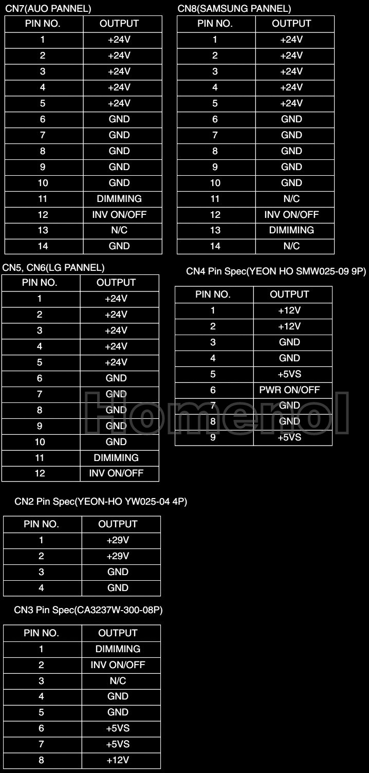
POWER PCB voltages

Other connector voltages
Power board [SMPS] schematic

Service mode

Typical Symptoms of PCBs problem
or bad connection
A. Symptom of initial latch up
- Define initial latch up : When turn on the power, both LEDs light up red and TV is not working.
- Repairing method : This is typical symptom when ROM(ICU3) is incorrectly connected at socket. So if you find this symptom, you must try to that ROM(ICU3) and socket have correct contact.
- As this method, TV set is not repaired, replace MAIN PCB.
B. Symptom of No image when LED and Back Light are working.
- Define No image : LED and BACK LIGHT of panel are correctly working but any image does not display.
- Repairing method : This is typical symptom when LVDS cable incorrectly connects.
So if you find this symptom, check LVDS connection.
- As this method, TV set is not repaired, replace Main or Sub PCB.
C. Representative Symptom caused by bad Connection between PCBs
=> Note: Dust or extraneous material may cause bad connections. Most of the time, applying soft brush, AIR FRESHIER, or breath to clean dust or extraneous materials can solve it. And then reassemble the Connector.

