Friday, 6 April 2018

JBL Flip 2 – Wireless Bluetooth Speaker - Disassembling procedure – How to remove the case – How to replace the speakers


JBL Flip 2
Begin by removing the rubber caps on both sides of the JBL Flip 2 by using the black spudger to get in between the creases.
Be very careful when removing the nfc rubber cap. There is a chip that is glued to the inside of the rubber cap. So, peel the rubber cap off slowly and remove the chip on the inside while peeling the rubber cap off.
Using the driver adapter with the number 1 Philip's head bit, remove the eight 7.0 mm screws on both sides of the JBL Flip 2.
The nfc chip is glued onto the side of the device. Use the black spudger to separate the mic from the surface.
Be careful not to sever the wire connecting the nfc chip to the inside of the device.
Gently slide the nfc chip into the device through the slot that the wire comes from.
Peel the black rubber piece from one end to the other.
Remove the two 7.0 mm screws using the driver adapter with the #1 Philip's head bit.
Carefully detach the silver plastic cover by pulling both ends off.
Pull both ends at the same time with the same amount of force to prevent the cover from breaking.
Separate the silver plastic piece by pulling it off from the middle.
Using the driver adapter with the #3.0 flat-head bit, pry out the 8 metal nibs on the back side of the speaker.
Repeat the same process for the 4 remaining metal nibs (two on each end).
Expand the metal casing and carefully slide it off the speaker.
Using the driver adapter, first insert the #4 socket into the driver; followed by the #1
Philip's head bit in order to reach the three 13.0 mm screws.
Using the classic spudger, get underneath the black tape strips found on both side of the device.
After lifting a portion of the tape off of the device, gently peel the tape off of the device, making sure to keep it intact.
There is another piece of tape on the side of the device with the control buttons. Lift the tape with the classic spudger and then peel the rest of the tape off.
Wedge a spudger between the two halves where the tape was to pry the device open. When working with electronics, it's important to choose a tool that's ESD-safe to avoid accidental damage to the device. The regular black nylon spudger or a plastic opening tool should be used whenever possible
Use the black spudger to disconnect the speaker cord from it's socket.
Use the black spudger to disconnect the auxiliary wire from its socket.
Carefully remove the cable connecting the control chip to the motherboard.
Using the black spudger, carefully remove the cord connecting the battery to the motherboard.
Carefully remove the cable connecting the nfc chip to the motherboard. Remove the two 7.0 mm Phillips #1 screws.
Remove the metal bar that was held in place by the screws. Unscrew the the other four 7.0 mm Phillips #1 screws around the speakers.
Gently remove the speakers from the slots.

Whirlpool Duet Front Loading Automatic washer - Error codes cause and solution


Whirlpool washing machine
ERROR - FH
No water detected entering machine or Pressure switch trip not detected.
If after 30 seconds the control does not detect water entering machine and then valves will be turned off and the error code will be displayed.
Or
If the control has turned the water valves on and after 8 minutes the flow meter has detected 10.5 gallons of water passing through it, but has not detected the
pressure switch trip, the valves will be turned off and the error code will flash.
Press PAUSE/CANCEL twice to clear the display.
Causes and Solution
# If there is no water in the unit:
Make sure that both valves at the water source(s) are turned on all the way.
Check for plugged or kinked inlet hoses or plugged screens in the inlet valves
Verify inlet valve operation
# If there is water in the unit:
Verify Drain pump operation.
Pressure Switch Hose is in good condition and properly connected to Tub and Pressure switch.
# Verify there is not a siphon problem.
# Verify wire harness connections to; Inlet Valves, Pressure Switch, Drain Pump, Flow Meter, and Central Control Unit (CCU).
# Check all hoses for possible leaks.
# Verify pressure switch operation.
# Verify flow meter operation.
# Verify CCU operation.
ERROR - F02
Long Drain If the drain time exceeds 8 minutes, the water valves are turned off and F02 is flashed.
Press PAUSE/CANCEL twice to clear the display.
NOTE: After 4 minutes the “Sud” error will be displayed, then 4 minutes later the F02 error code will be displayed.Causes and Solution
# Check the drain hose and make sure it is not plugged or kinked
# Check the electrical connections at the pump and make sure the pump is running.
# Check the drain pump filter for foreign objects.
# If the above does not correct the problem replace the pump.
ERROR - F05
Water temperature sensor error If during the water heating step in the wash cycle, the
water temperature sensor (NTC) value is out of range, or
the heating element circuit has failed, the F05 error code
will be displayed.Causes and Solution
# Check the Water Temperature Sensor, Heating Element and Element Relay
# Check connections to the Sensor, Heating Element and Relay
ERROR - F06
Drive motor tachometer error The control is unable to properly detect motor speed and
the machine will shut down. If a failure occurs during
high-speed spin the door will be unlocked after 3
minutes.Causes and Solution
# Check wire harness connections between the Drive Motor/Tachometer and the Motor ControlUnit (MCU), and between the MCU and the Central Control Unit (CCU)
# Check the Drive Motor
# Check the MCU
# Check the Wire Harness
ERROR - F07
Motor control unit error The Central Control Unit has detected a short in the motor control unit. If a failure occurs during high-speed spin the door will be unlocked after 3 minutes.Causes and Solution
# Check wire harness connections between the Drive. Motor and the Motor Control Unit (MCU), and between the MCU and the Central Control Unit (CCU).
# Check the MCU.
# Check the Drive Motor.
# Check the Wire Harness.
ERROR - F09
Overflow condition If the Overflow contact on the pressure switch is Closed for more than 60 seconds an Overflow condition will occur. In an Overflow condition, the Door will remain locked, and the Drain Pump will run constantly, even if PAUSE/CANCEL is pressed twice and the Display is cleared. Unplug the unit to service.Causes and Solution
# Check the drain hose and make sure it is not plugged or kinked
# Check Wire Harness connections to the Drain Pump, Pressure Switch, and Central Control Unit (CCU).
# Check / Clean Drain Pump Filter of foreign objects.
# Check for Drain Pump Failure.
# Check the Inlet Valve for proper shut off.
# Check the Pressure switch for proper operation.
ERROR - F10
Motor Control Unit (MCU) heat sink thermal trip
If the thermal protector on the MCU heat sink gets too hot, it will open the thermal protector on the heat sink which will stop motor functions and an F10 will be displayed.Causes and Solution
# Check for Proper Installation, verify the unit is not located near a source of heat and has proper ventilation.
# Check Wire Harness connections to the MCU, the motor, and Central Control Unit (CCU).
# Check the Drive system for any worn or failed components.
# Check MCU.
# Check Motor.
ERROR - F11
Serial communication error Communication between the Central Control Unit (CCU) and the Motor Control Unit (MCU) cannot be sent correctly.Causes and Solution
# Check Wire Harness connections to the MCU, the motor, and Central Control Unit (CCU).
# Check the Drive system for any worn or failed components.
# Check MCU.
# Check CCU.
# Check Motor.
# Check Wire Harness.
ERROR - F13
Dispenser circuit error If the dispenser motor is not able to be driven to it’s proper position.Causes and Solution
# Check mechanical linkage from dispenser motor to the top of the dispenser.
# Check Wire Harness connections to the dispenser motor and Central Control Unit (CCU)
# Check Dispenser Motor.
ERROR - F14
EEPROM error The Central Control Unit (CCU) receives it’s data from an EEPROM onboard the CCU. If there is an error reading this data it will cause this error.Causes and Solution
# A power glitch may cause this error. Try unplugging the Unit for two minutes to see if that fixes the error.
# Check CCU.
ERROR - F15
Motor Control Unit (MCU) error If the MCU detects multiple resets or errors during a
wash cycle it will go into this error mode.Causes and Solution
# Check Wire Harness connections to the MCU, the motor, and Central Control Unit (CCU).
# Check Drive belt.
# Check MCU.
# Check Motor.
# Check Wire Harness.
ERROR - Sud
SUDS LOCK (Overdose of detergent detected during the wash cycle)
The motor control unit senses a suds lock condition by analyzing the current draw on the drive motor. If “Sud” is displayed a potential suds lock is detected. This may signify a bad pump, an extra heavy load, excessive detergent, or excessive suds.Causes and Solution
# If too much detergent was used, run the unit through a Rinse/ Spin cycle then a Normal cycle without adding any detergent. This should clear the unit of the excess detergent.
# Check the drain hose and make sure it is not plugged or kinked.
# Check Wire Harness connections to the Drain Pump, Pressure Switch, and Central Control Unit (CCU).
# Check / Clean Drain Pump Filter of foreign objects.
# Check Drain Pump.
# Check the Pressure Switch.
# Check CCU.
FdL Door lock error A Door Lock Error occurs if the door cannot be locked. It will try to lock it 6 times before displaying the error.Causes and Solution
# Door Lock Mechanism broken or removed from the Door.
# Check Door Lock/Switch Assembly.
# Check the wire harness connections to the Door Lock/Switch Assembly and Central Control Unit (CCU).
# Door Lock/Switch Assembly Failure.
ERROR - FdU
Door unlock error A Door Unlock Error occurs if the door cannot be unlocked. It will try to unlock the door 6 times before displaying the error.Causes and Solution
# Door Lock Mechanism broken.
# Check Door Lock/Switch Assembly for foreign objects
# Check Wire Harness connections to the Door Lock/Switch Assembly and Central Control Unit (CCU)
# Door Lock/Switch Assembly Failure Replace failed component.
Note: The door lock/switch assembly can be manually unlocked.
To Manually unlock the door lock system:
1. Unplug the power cord from the outlet.
2. Remove the lower toe panel.
3. Reach up along the inside of the front panel and locate the bottom of the door latch assembly.
4. Located on the bottom of the door latch assembly is a tear-drop shaped tab.
5. Gently pull the tab down about 1/4 inch or until a click is heard.
6. The door may now be opened.

Thursday, 5 April 2018

Brother computerized Sewing machine Timing belt and motor belt tension adjustments - Presser bar height adjustment – Test mode


Brother computerized Sewing machine – Brother SUPER GALAXIE 3100D - ULT2001N - ULT2001C - M3000N - ULT2003D – Timing belt and motor belt tension adjustments - Presser bar height adjustment – Test mode
Brother computerizes Sewing machine
TENSION OF MOTOR BELT AND TIMING BELT
STANDARD
There should be a 1.5-3.5 mm slack in the motor belt when the center of the motor belt is pressed with a force of 1N (100g). There should be a 3-4 mm slack in the timing belt when it is pressed with a force of 2N (200g).
ADJUSTMENT
Timing belt
1. Loosen the screw of the belt adjusting pulley.
2. Adjust the position of the belt adjusting pulley.
3. Tighten the screw of the belt adjusting pulley.
Motor belt
1. Loosen the two screws securing the motor holder.
2. Adjust the belt tension by moving the motor holder.
3. Tighten the two screws.
Adjustment Points
1. If the timing belt tension is too loose, the belt may jump while sewing on denim and other thicker fabrics or overlapping fabric, or the feed timing or the closeness of the needle and rotary hook may prevent sewing.
2. If the motor belt tension is too tight, the torque becomes too much, causing the motor to rotate slower and generate an irregular noise.
3. If the motor belt tension is too loose, the belt may jump and the upper shaft may not rotate smoothly while sewing on denim and other thicker fabrics or overlapping fabrics, the motor may not rotate smoothly, or the upper shaft may not rotate.
NEEDLE DOWN POSITION ADJUSTMENT
STANDARD
When test mode "4" is selected, the needle should be exactly at the middle of the needle plate hole in the needle down position.
ADJUSTMENT
1. Select test mode "4".
2. Turn the balance wheel to move the needle to the needle down position.
3. Loosen the screw securing the zigzag connecting rod assembly.
4. Press the keys on the display to move the needle to the left and right, and then turn the zigzag adjusting nut by using the box wrench to set the needle in the center of the needle hole.
5. Tighten the screw securing the zigzag connecting rod assembly.
6. Press the keys on the display to move the needle to the left and right and check the needle down position.
Test mode for main PC board only
(3-point needle drop, alarm check)
1. Turn on the power with the front cover removed.
2. Press the SW5 switch.
The main seam position will change each time it is pressed: left seam position  middle seam position  right seam position.
3.
# Press the SW1 switch, make the feed 0, and operate at the lowest speed.
# By pressing the SW3 switch, the conditions will change as follows:
Low speed (70 RPM) Feed = 0 (Original condition)
In the conditions described above, press SW5 to change the seam position without regard to the needle position:
left seam position > right seam position  left seam position …
Medium speed (410 RPM) Feed = 0
In the conditions described above, press SW5 to change the seam position without regard to the needle position:
left seam position > right seam position  left seam position …
High speed (850 RPM) Feed = 0
In the conditions described above, press SW5 to change the seam position without regard to the needle position:
left seam position  right seam position >  left seam position …
High speed (710 RPM) triple zigzag Feed = Maximum (4mm), Z = Maximum (7mm)
Low speed (70 RPM) Feed = 0
NEEDLE BAR HEIGHT
STANDARD
When test mode "5" is selected, turn the balance wheel so that the needle meets the rotary hook point. At this time, the clearance between the upper end of the needle eye and the bottom of the rotary hook point should be 1.0-1.4 mm.
ADJUSTMENT
1. Select test mode "5".
2. Turn the balance wheel so that the needle meets the rotary hook point.
3. Loosen the screw of the needle bar block assembly.
4. Move the needle bar vertically to adjust the clearance to between 1.0-1.4 mm.
5. Tighten the screw of the needle bar block assembly.
NOTE :The needle bar clamp should be parallel to the side of the needle plate. If the needle bar is loose when you adjust the needle bar height, it may result in sewing troubles.
Adjustment Points
1. If the needle bar height is too low or too high, skipped stitches, split thread or cut thread may occur.
2. While adjusting the needle bar height, check the needle threading hook.
PRESSER BAR HEIGHT
STANDARD
The clearance from the needle plate top to the bottom of the presser bar should be 7.0-7.5 mm.
ADJUSTMENT
1. Raise the presser foot lifter.
2. Loosen the screw of the presser bar guide bracket.
3. Adjust the height of the presser bar by moving it vertically.
4. Tighten the screw of the presser bar guide bracket.
NOTE :The presser foot should be positioned in the center of the needle hole of the needle plate.
Adjustment Points
1. Install presser foot J.
2. When adjusting the presser bar height, the presser foot should be parallel with the feed dog hole in the needle plate.
# A hexagonal pencil can be used to check the height.
3. If the presser foot is not parallel with the feed dog hole, the needle may contact the presser foot or the fabric may not feed straight while overcasting.
# After the presser bar height is adjusted, be sure to adjust the fabric thickness detector using test mode "2".
TIMING BELT TENSION FOR THE X DIRECTION
STANDARD
There should be 4 mm slack in the timing belt looped around the X driving shaft and the X tension pulley shaft, when the center of the belt is pressed by a force of 1.2 ± 0.12N (120 ± 10g) after the X carriage unit is moved all the way to the right.
ADJUSTMENT
1. Move the X carriage unit all the way to the right.
2. Loosen the screw of the X tension pulley.(screws (A) and (B))
3. Adjust the position of the X tension pulley.
4. Tighten the screw of the X tension pulley.(screws (A) and (B))
Adjustment Point
If the tension in the belt is too weak or too tight, the embroidery may not be aligned correctly (the inside of the pattern may not align with the outline).


Samsung Galaxy S4 – How to replace the Mini USB board


Samsung Galaxy S4
Keep press the END key to turn off the phone (if turned on).
Pull out the back cover of the cell phone with the help of a plastic opening tool.
Pull up the battery.
Remove the SIM Card by sliding it towards the bottom of the device.
Using your fingernail push through the hole at the top of the memory card holder, so it can be slid out.
Remove the 10 4.0 mm Phillips screws on the back of the phone using the #00 Phillips screwdriver. Not needed, but Tweezers can be helpful in removing the screws from their holes, as their size makes removal a tad difficult.
Starting at the USB port, slide a plastic tool around the perimeter of the phone between the rear housing and frame. As you work your way around the edge you will feel the clips release.
Carefully separate the rear housing and the mid-frame to reveal the inside of the phone.
Remove the 2 flex cables shown that attach to the USB board, Tweezers can be especially helpful here.
Gently pry underneath the charging port using the plastic opening tool to separate it from the double sided tape below.
Once its released, gently lift the main board and remove the USB board containing the charging port.


Lenovo G70-35 – How to remove the HDD – How to test the adapter voltage


Lenovo G70-35
To verify a symptom, follow the steps below:
1. Turn off the computer.
2. Remove the battery pack.
3. Connect the AC adapter.
4. Make sure that power is supplied when you turn on the computer.
5. Turn off the computer.
6. Disconnect the AC adapter and install the charged battery pack.
7. Make sure that the battery pack supplies power when you turn on the computer.
If you suspect a power problem, see the appropriate one of the following power supply checkouts:
“Checking the AC adapter”
“Checking operational charging”
“Checking the battery pack”
Checking the AC adapter
You are here because the computer fails only when the AC adapter is used.
If the power-on indicator does not turn on, check the power cord of the AC adapter for correct continuity and installation.
To check the AC adapter, follow the steps below:
1. Unplug the AC adapter cable from the computer.
2. Measure the output voltage at the plug of the AC adapter cable. See the following figure:
Note: Output voltage for the AC adapter pin No. 2 may differ from the one you are servicing.
3. If the voltage is not correct, replace the AC adapter.
4. If the voltage is acceptable, do the following:
Replace the system board.
Note: Noise from the AC adapter does not always indicate a defect.
Checking operational charging
To check whether the battery charges properly during operation, use a discharged battery pack or a battery pack that has less than 50% of the total power remaining when installed in the computer.
Perform operational charging. If the battery status indicator or icon does not light on, remove the battery pack and let it return to room temperature. Reinstall the battery pack. If the charge indicator or icon is still off, replace the battery pack.
If the charge indicator still does not light on, replace the system board. Then reinstall the battery pack. If it is still not charged, go to the next section.
Checking the battery pack
Battery charging does not start until the Power Meter shows that less than 95% of the total power remains; under this condition the battery pack can charge to 100% of its capacity. This protects the battery pack from being overcharged or from having a shortened life.
To check your battery, move your cursor to the Power Meter icon in the icon tray of the Windows taskbar and wait for a moment (but do not click it), and the percentage of battery power remaining is displayed. To get detailed information about the battery, double-click the Power Meter icon.
Note: If the battery pack becomes hot, it may not be able to be charged. Remove it from the computer and leave it at room temperature for a while. After it cools down, reinstall and recharge it.
Battery pack
Unlock the manual battery latch 1. Slide the spring-loaded latch to the unlocked position to eject the battery pack 2. Lift up the inner edge of the battery pack, pivoting it on the outer edge 3 . Slide the battery pack in the indicated direction to remove it 4.
Hard disk drive(HDD)
Loosen the screws 1 that secure the compartment cover. Remove the compartment cover 2
Remove the frame fixing screws 1
Push the hard disk drive. 

Samsung Galaxy S II – Disassembling – How to replace the USB charging port


Samsung Galaxy S II 
Remove rear casing and battery.
Remove SD card and sim card (if needed).
Remove each of the 7 phillips head screws.
Move along the outside edge with the plastic tool, popping the connections to the phone
The volume rocker and power button housing can be easily lost when you remove the back housing. Make sure you keep it where you can find it.
Remove the 2 black phillips head screws located at the top left and the bottom right of the logic board.
Disconnect all push connectors and the antenna cable on the left. They detach easily with a small pull.
Prop the motherboard on the side of the phone
Remove the 2 phillips head screws located at the bottom of the charging board
Remove board by prying off one end and moving toward the other.
A hair dryer can help loosen the adhesive, but is optional.
Place the new board where the old board was.


Western Digital My Book – External Hard Drive – Disassembling procedure – How to replace the mini USB Port


Western Digital My Book
Turn the drive to its backside.
With the plastic opening tool, fit the pry along the edges of the case.
When you hear the case snap-out of its fitted grooves, go ahead slowly slide the board assembly out of the case.
Gently pull the three pronged, clear plastic piece from the inserted rubber holder.
Unscrew the 2 screws from the motherboard.
Remove all the rubber pieces from the four corners to unhinge the motherboard.
Safely remove the motherboard. Set aside in a safe static-free location.
Grab the mini USB and align it with the appropriate metal docks on the motherboard.
Soldering Iron is extremely hot.
Please do not touch the iron tip.
Start heating up the Soldering Iron, may take about 10–15 mins.


LG 32LK610BPUA, LG 32LK610BBUA LCD TVs – How to upgrade the software, fault checking method

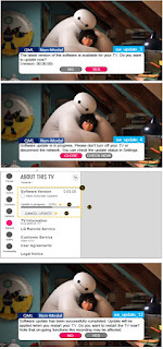
  Software update procedure USB (1) Insert the USB memory Stick to the USB port (2) Automatically detect the SW Version and show the bel...