Monday, 9 January 2017

How can we detect and rectify problems of Fisher and Paykel washing machine

Fisher and Paykel  SMART DRIVE ELECTRONIC WASHING MACHINE PHASE 1 to 5 – 230v problems and solutions
SMARTDRIVE PROBLEMS
If Smartdrive Appears To Have No Power
If the module appears to be dead / no power then check the following:-
* Is the external mains plug switched on and live?
* Are all plugs connected into the Motor Controller?
* Phase 4 Only. Check that the product is not "asleep". There is a mode in the motor controller where it can shut down in the event of a transient on the mains. This can be caused by the thermal trip on the pump, i.e. pump block. If this occurs the module will not restart unless the power is turned off at the wall for at least 90 seconds. The module is not damaged and there is no need to replace the motor controller.
* Phase 5 Only. The pump is used as part of the power supply if it is not connected Smartdrive will appear dead. Check the pump resistance is 33 ohms. If the pump is open circuit, has the thermal cut out tripped? This should reset within 15 minutes after tripping once the pump has cooled down. If the thermal cut out has tripped, check for a blocked pump.
* Check the resistance from Phase & Neutral to Earth. This will identify if either the motor wiring harness or the lid switch harness is shorting to the wrapper.
* Check that the resistance of each of the water valves is 15 ohms (phase 1-4), 64 ohms (Phase 5).
Phase 2-4 Only. Check the 15v supply is 11v min, 17v max.
Phase 1 Only. If fitted with an original Phase 1 Motor Controller with a fuse, see WM51
Replace the Motor Controller, if none of the above faults are found.
NB. Ensure product is empty of water when pressure tube is reconnected. If the product is phase 1 to 4, ensure that the console area is dried out before fitting replacement motor controller. Always check the pump resistance before fitting a new Motor Controller.
If Smartdrive Powers Off mid cycle
* If there is a power interruption while Smartdrive is performing a wash cycle, Smartdrive will continue when power returns. There are two exceptions.
* Phase 4 Only. Check that the product is not "asleep". There is a mode in the motor controller where it can shut down in the event of a transient on the mains. This can be caused by the thermal trip on the pump, i.e. pump block. If this occurs the module will not restart unless the power is turned off at the wall for at least 90 seconds. The module is not damaged and there is no need to replace the motor controller.
* Phase 5 Only. The pump is used as part of the power supply, if the thermal trip goes on the pump the product will power off and the cycle will not restart. The thermal cut-out will normally only trip on the pump if there is a pump block.
Flooding
* Check inlet hoses are not leaking.
* Check drain hose is inserted correctly, and that the drain is not blocked.
* Check water valves are not jammed on, or dripping when off.
* Has the pressure pipe been connected when the bowl contained water? The pressure pipe must be connected when the bowl is empty, otherwise flooding may occur on the next cycle. Alternatively Smartdrive may get Fault Code 11.
* Often caused by Smartdrive leaking or over sudsing. See section 6.4.
* The pressure transducer in the Motor Controller is faulty, but only if showing a fault code.
Leaking
* Check for obvious signs of leaks from taps, inlet hoses, inlet washers, water valves and mixing chamber. There should be no signs of water within the topdeck area.
* Check for obvious signs of leaks in the standpipe, drain hose, pump, and air bell. The pump can leak if the pump bracket is not secured properly.
* Check size setting of Smartdrive is correct.
* Check that the high water level is acceptable. Acceptable limits are 10-110mm from the top of the agitator to the water. If it is less than 10mm, then splashing may be a
problem. Empty bowl, remove then refit pressure pipe to Motor Controller, then retest. If water level is outside these limits, replace Motor Controller.
* If all these fail the best way to check leaks is to fill the bowl with water and detergent and identify the leak point. If there is no service hatch, the feet may be fully extended.
* Otherwise it could be that Smartdrive was overloaded or in a humid environment. Too much detergent could have been used.
* Phase 1-3. A new neck ring for the outer bowl will reduce ‘phantom’ suds leaks. Changing the impellor on the pump should also reduce the incidence of these leaks.
* Phase 1. See WM65 in the Appendix B. Water can leak onto the floor during spin.
Noisy
If the user is complaining about noise it may be in a number of different areas. Is the noise during spin? Is it a banging sound, this would typically be the drain hose, inlet hoses, mains lead or harness. If it is an out of balance noise check level, bias spring and balance rings. If it is a ‘clunk’ that occurs up to 3 times per cycle, this would be a bowl check. It occurs when Smartdrive is draining and ¾ empty. This is a ‘feature’ and a noise that cannot be reduced.
* Is Smartdrive level and on all four feet equally.
* Check the mains lead, inlet hoses and drain hose outside the wrapper, behind Smartdrive.
* Check the harness and drain hose inside is not banging on the wrapper during spin.
* Check bias spring is fitted correctly.
* Check the 2 balance rings in the inner bowl contain water. Check weights.
* Check for noisy suspension rods. Phase 1 was noisy during Stir.
* If the inner bowl or agitator is noisy check for obstruction. Check the spline drive is clean. If there is a grating sound check the single stainless steel washer beneath the spline drive.
* If the motor is abnormally noisy. Some early phase 5 rotors were noisy and replacement may rectify this. Chipped or cracked rotor magnets are unlikely to affect the noise.
* If the pump is noisy. Check for obstruction. Change parts as necessary.  The Motor Controller or Display will not be faulty.
Continuous Spinning or Slow Spinning
There have been some reports of ‘continuous spinning’. This statement is a bit misleading as Smartdrive will always ensure that the motor will not spin continuously. However, it could be one of the following:-
The most likely cause of slow or continuous spinning is ‘Out of Balance’. To correct this see section 10.5.
Normally the Out of Balance correction is to slow down or stop and retry to spin. Smartdrive will typically retry this 3 times before giving an out of balance user warning. If the out of balance recovery is set to enabled, see section 7.6 (Phase 3-5). Smartdrive will refill the bowl with water to redistribute the load. Smartdrive will only try this once before sounding a user warning.
Intermittent Lid switch. Check resistance and operation of the lid switch.
Spray Spin & suds. Too much detergent can cause final spin to stop and respin 4 times. This is due to suds build up between the bowls. Normally get a suds user warning.  A less likely cause of slow spinning is the ‘hot bowl flag’. Smartdrive activates this flag after a Hot or Warm Hot fill. Smartdrive will only spin to 700RPM. The outer bowl plastic will not withstand a 1000RPM spin if it is hot. This flag may be cleared in Diagnostic mode. Phase 1 can inadvertently set the ‘hot bowl flag’, if the warm or hot fill cycle is interrupted. This will restrict the maximum spin speed to 700 RPM.  The Motor Controller or Display will not be faulty.
Poor Wash Performance
Linting. There are no serviceable parts or filters associated with linting.
Wash Performance. Check the following: -
* Ensure the user selects the correct water level for the wash load.
* Check the size is set correctly, see section 9.0.
* Check the High Water level is within limits as defined in section 6.4. If the water level is outside these limits then replace the motor controller.
* If auto water level is being used and not selecting the correct water level, this may be modified.
* If fabric softener is used this can build up within the outer bowl. This can result in black flakes present in the wash load. If this is a problem it is recommended that Smartdrive is periodically filled with hot water, plus one to two cups of dishwashing powder and left to soak.
> If the water levels are correct the Motor Controller or Display will not be faulty.
Siphoning
Typically this occurs when the Standpipe height is too low. The minimum is 850mm from the floor, this is 90mm ABOVE the drain hose outlet on Smartdrive. With a very low standpipe and a very high water level this could result in water pouring down the standpipe prior to Smartdrive completing fill and resulting in no water in bowl during agitate. This could result in fault code.
* If the drain hose is pushed too far into the standpipe or drain, Smartdrive will siphon during rinse, which could result in a ‘No Taps’ user warning.
* Siphoning can result from a restricted drain hose or partial pump block.  The Motor Controller or Display will not be faulty.
Radio Frequency Interference (RFI)
Smartdrive complies with international standard CISPR 14.2. Check the earthing of the wrapper.
Otherwise if the user is having poor TV reception it is most likely to be that the TV aerial or reception is inadequate. Recommend an improved aerial or an amplifier for TV aerial.
Earth Leakage
* If the resistance from earth to Phase/Neutral is low, below 1M ohm, check the following:-
* Is the main motor harness shorting to earth?
* Phase 3 to 5. Is the lid switch harness shorting to the wrapper?
* Are there any other connections to earth?
* If the earth leakage resistance is OK and the earth leakage breaker trips check that this breaker is not of an older type. Earth leakage protection devices are designed to trip when the earth leakage current is 15-30mA. The older designs tripped in less than 30ms, while more modern designs are up to 100ms. Consequently older devices are more susceptible to false tripping than modern ones.  Smartdrive complies with all the international requirements regarding earth leakage.
It Appears Smartdrive is doing nothing
The user may have stopped Smartdrive before detecting a user warning or fault.
* Check that the lid switch is working.
* Check that the water is connected and taps on.
* If Delay start is ON then the ‘Start/Pause’ button will do nothing.
* If Smartdrive is bowl checking continuously: Check for oversudsing or a foreign object preventing the clutch from re-engaging.
* If Auto Water Level is being used: NB. Smartdrive resenses Auto Water Level every time the lid is opened.
* If the water valves are pulsing: This is an indication that Smartdrive is attempting to restart but is identifying a fault condition. Go to next step.
* Turn Restart OFF and let Smartdrive diagnose the fault.
RESTART
If a problem occurs in Smartdrive, it will try to correct the problem and retry. Smartdrive will rectify any problems of a temporary nature. If there is a continuous problem Smartdrive will retry several times. This process may take up to 10 minutes depending on the type of problem. If Smartdrive still cannot resolve the problem, the fault code is displayed and Smartdrive will beep continuously. RESTART ON is the default state. This forces Smartdrive to retry when a problem occurs. While servicing Smartdrive turn
RESTART OFF. This will allow any fault in the system to show up immediately.
 To enter Diagnostic Mode turn the power on at the power point and off at the console. Press and hold the WASH TEMPERATURE DOWN button then press the POWERbutton. Smartdrive will give 2 short beeps. Phase 3 Only press ADVANCE button once. From Diagnostic mode use the WATER LEVEL DOWN button to turn the RESTART on or off.
LOW WATER LEVEL LED OFF = RESTART OFF.
LOW WATER LEVEL LED ON = RESTART ON. (Default)
RESTART status can be easily identified when Smartdrive is first turned on -
* If none of the 5 leftmost green wash progress LEDs are on, the RESTART is on.
* If the 5 leftmost green wash progress LEDs are flashing, the RESTART is off.
NB: RESTART is a service aid only and should be left ON in the customer’s home. To return to normal operation, and to reset the RESTART feature to the default setting, power off Smartdrive.
RECYCLE
After servicing, Smartdrive may require an extended test where Smartdrive can be left to complete a number of wash cycles. By turning on RECYCLE Smartdrive will continuously repeat the selected wash cycle until RECYCLE is turned off.
Enter Diagnostic mode as described above (RESTART). Use the WATER LEVEL UP button to turn RECYCLE on or off.
MEDIUM WATER LEVEL LED ON = RE-CYCLE ON.
MEDIUM WATER LEVEL LED OFF = RE-CYCLE OFF. (Default setting).
RECYCLE status can be easily identified when Smartdrive is first turned on: -
* If the 3 rightmost rinse and spin progress LEDs are on, recycle is off.
* If the 3 rightmost rinse and spin LED’s flash, recycle is on.
NB. Recycle is designed as a service aid only and should be OFF in the customer’s home. To return to normal operation, and to return recycle to the default setting, power off Smartdrive.

Sunday, 8 January 2017

LG Mini Hi-Fi System CM9530 – How to troubleshoot and rectify No Sound fault

Most of us might get stunned for a while, when our sound system malfunction all of a sudden.  If you have some knowledge in electronics, and have test instruments, yourself can troubleshoot and rectify the problem.  I’ve done it myself, when my LG sound system has gone dead.  Here I publish the procedure I did follow to rectify that fault.  It too about two more days for me, as I’m not well experienced in service work.  Patience and concentration are the most for this work.
[Check the speaker and all connection related to it [including the speaker wire continuity and connections, and make sure all of it are OK, belfore doing anything]
NO SOUND
There is no sound output in the CD FUNCTION, repair the set according to the following guide.
IN THE CD FUNCTION
Solution
Please check and replace IC501, IC600 on MAIN board.
How to troubleshoot (Countermeasure)
1) Check CD_BCK, CD_LRCK, & CD_DATA signals from IC407 to IC501.
 If no signal, check if the RF & servo signals from MD is entered to IC407.
Refer to the “No operation of MD” guide.
2) Check the following I2S signal flow. < I2S audio signal Interface >
- MCS_BCK : IC501_pin4 --> IC600_pin23
- MCS_LRCK : IC501_pin5 --> IC600_pin22 (44.1 kHz)
- MCS_DATA_OUT : IC501_pin85 --> IC600_pin24
- MCS_MCLK : IC501_pin3 --> IC501_pin82
 If there is any trouble, check the power for each IC. The power is normal but, if the signal waveform to the IC is distorted or no signal, replace it with a new one.
3) Check if “Digital audio AMP block”.
NO SOUND
There is no sound output in the USB FUNCTION, repair the set according to the following guide.
IN THE USB FUNCTION
Solution
Please check and replace IC501, IC504 on MAIN board & IC3U01 on USB board.
How to troubleshoot (Countermeasure)
1) Check +5VU to USB board.
 If +5.6 VA to pin2 of IC352(LDO) doesn’t come out, check pin2, 3 of CN351.
 If +5.6 VA is normal & +5VU of IC352 pin3 doesn’t come out, then replace IC352.
2) Check USB D± from main board to USB board.
a. Check USB_HUB_DN/DP signals to IC501(pin16, 18)
b. Check USB1/2_DN/DP signals from IC501 to CN502 (pin5, 6, 8 & 9)
 If there is any trouble, check the power for each IC. The power is normal but, if the signal waveform to
the IC is distorted or no signal, replace it with a new one.
3) Check if “Digital audio AMP block”.
NO SOUND
There is no sound output in the AUX FUNCTION, repair the set according to the following guide.
IN THE AUX FUNCTION
Solution
Please check and replace IC202 on MAIN board.
How to troubleshoot (Countermeasure)
1) Check AUX_L/R signals to IC202 (Pin23, 24).
2) Check if MCS_BCLK, MCS_LRCLK, & MCS_MCLK are entered from IC501 to IC202.
3) Check if ADC/MIC_DATA is entered from IC202 to IC501.
 If no signal, check +5 V & +3.3 V(ADC) for IC202. If is NG, replace it a new one.
4) Check the following I2S signal flow from IC501 to IC600. (Refer to Item 6-1.)
 If there is any trouble, check the power for each IC. The power is normal but, if the signal waveform to
the IC is distorted or no signal, replace it with a new one.
5) Check if the digital audio AMP block is okay. Refer to “Digital Audio AMP” guide.
 If AMP is damaged, replace it with a new one.
NO SOUND
There is no sound output in the PORT. IN FUNCTION, repair the set according to the
following guide.
IN THE PORT. IN FUNCTION
Solution
Please check and replace IC202 on MAIN board.
How to troubleshoot (Countermeasure)
1) Check PT_L/R signal from MIC/PTB board to MAIN board.
2) Check POT_L/R signals to IC202(Pin9, 10).
3) Check if ADC_BCK, ADC_LRCK, & DAC_MCLK are entered from IC501 to IC202.
4) Check if ADC_DATA is entered from IC202 to IC501.
 If no signal, check +5 V & +3.3 V(ADC) for IC202. If is NG, replace it a new one.
5) Check the following I2S signal flow from IC501 to IC600. (Refer to Item 6-1.)
 If there is any trouble, check the power for each IC. The power is normal but ,
If the signal waveform to the IC is distorted or no signal, replace it with a new one.
6) Check if the digital audio AMP block is okay. Refer to “Digital Audio AMP” guide.
 If AMP is damaged, replace it with a new one.
NO SOUND
There is no sound output in the TUNER FUNCTION, repair the set according to the following guide.
IN THE TUNER FUNCTION
 Solution
Please check and replace IC202, TU101 on MAIN board.
How to troubleshoot (Countermeasure)
1) Check if TUNER_LR is entered from Pin1 & 3 of TU101 to IC202(Pin23, 24).
 If no signals, Check +3.3 V for Tuner power.
 Check if the Tuner control signals (CLK, DAT, CE, RST, GPO2) are entered from IC101 to TU101.
If it doesn’t work, replace TUNER with a new one.
2) Check if MCS_BCK, MCS_LRCK, & MCS_MCLK are entered from IC501 to IC202.
3) Check if ADC/MIC_DATA is entered from IC202 to IC501.
 If no signal, check +5 V & +3.3 V(ADC) for IC202. If is NG, replace it a new one.
4) Check the following I2S audio signal flow from IC501 to IC600. (Refer to Item 6-1.)
 If there is any trouble, check the power for each IC. The power is normal but, if the signal waveform to
the IC is distorted or no signal, replace it with a new one.
5) Check if the digital audio AMP block is okay. Refer to “Digital Audio AMP” guide.
 If AMP is damaged, replace it with a new one.
NO SOUND
There is no sound output in the MIC IN FUNCTION, repair the set according to the following guide.
IN THE MIC IN FUNCTION
Solution
Please check and replace IC202 on Main Board or ICM101 on MIC board.
How to troubleshoot (Countermeasure)
1) Check MIC_SIG signal to Pin10 of CN200.
 If no signal, Check the signal to Pin1 of CNM101 on the MIC board.
2) Check if MIC_SIG is entered from Pin1 of CNM101 to Pin3 of IC506 (MIC AMP).
3) Check if the amplified signal is entered from Pin4 of IC506.
 If no signal output, check +12 V for IC506, replace IC506 with a new one if it has a problem.
4) Check if MCS_BCK, MCS_MLCK & MCS_LRCK is entered from IC501 to IC202.
 If no signal, check +5 V & +3.3 V for IC508. If it is abnormal, change replace it a new one.
5) Check if the digital audio AMP block is okay. Refer to “Digital Audio AMP” guide.
 If AMP is damaged, replace it with a new one.
NO SOUND
There is no sound output in the BLUETOOTH FUNCTION, repair the set according to
the following guide.
IN THE BLUETOOTH FUNCTION
Solution
Please check and replace IC501 on MAIN board and Bluetooth module on front panel.
How to troubleshoot (Countermeasure)
1) Check BT_RX, BT_TX signal to Pin5, 7 of CN504.
 If no signal, check the signal to Pin5, 7 and Pin1(+3.3 V) of on the Bluetooth module and cable connection state.
 If there are no signal out from module, replace new module.
2) Check if BT_RX/TX is entered from Pin5, 7 of CN504 to Pin169, 170 to IC501 (DSP).
3) Check if MIC_BCK, MIC_MLCK & MIC_O_DATA is entered from IC501 to IC600.
 If no signal, check VCC12(+1.2 V) for IC501. If it is abnormal, change replace it a new one.
4) Check the following I2S signal flow from IC501 to IC600.
 If there is any trouble, check the power for each IC. If the signals are abnormal, replace it a new one.
5) Check if the digital audio AMP block is okay. Refer to “Digital Audio AMP” guide.
 If AMP is damaged, replace it with a new one.
AUDIO OUTPUT IS SMALL OR NO AUDIO OUTPUT
Audio signal output is small or not. when you power on the Middle Power Mini System.
 IC700 ~ IC705
Solution
Please check and replace IC700 ~ IC705 on MAIN board.
How to troubleshoot (Countermeasure)
1) Please check if this system is on bass blast mode.
 C, RL and RR make sound only on bass blast mode.
2) Check the IC700 ~ IC705 on your eyes.
3) Check the audio signal output check (Pin13 of IC700 ~ IC705).
First, check the Audio Data input (Pin3 pin of IC700 ~ IC705).
4) If the audio signal output has no output, try to change IC which has no output.
5) Lastly, check Speaker Terminal (TM700).

Tuesday, 3 January 2017

How to disassemble the LG MA3281T LIGHT OVEN “Steam Solar DOM” – microwave oven

Disassemble procedure
OUTER CASE REMOVAL
1) Disconnect the power supply cord from the outlet.
2) Remove the screws from the rear and along side edges of the case.
The outer case must be moved backward to be lifted off.
POWER SUPPLY CORD
1) Remove the outer case.
2) Disconnect two terminals, and remove one screw of the earth terminal.
CAUTION: DISCHARGE THE HIGH VOLTAGE CAPACITOR BEFORE SERVICING
DOOR GROSS ASSEMBLY REMOVAL
1) Disconnect the power cord.
2) Remove the outer case.
3) Disconnect the leadwire from the reley PCB.
4) Open the door from oven. insert “JIG ” into the choke cover hole of door.
5) Lift the door from front cavity.
NOTE:
1. After replacing the door, be sure to check that the primary switch, monitor switch, and secondary switch operate normally.
2. After replacing the door, check for microwave energy leakage with a survey meter. Microwave energy must be below the limit of 5 mW/cm2. (with a 275 ml water load)
3. When mounting the door assembly to the oven assembly, be sure to adjust the door assembly parallel to the chassis. Also adjust so the door has no play between the inner door surface and oven frame assembly. If the door assembly is not mounted properly, microwaves may leak from the clearance between the door and the oven.
MAIN PCB ASSEMBLY
1) Remove choke cover for door assemply.
2) Remove the two screws holding PCB bracket.
3) Remove PCB bracket.
4) Disconnect two leadwires from Main PCB.
5) Remove the seven screws holding Main PCB.
6) Remove the Main PCB from door assembly.
NOTE:
1. Be sure to use now choke cover assembly when you reassembly PCB assembly.
REAR COVER ASSEMBLY REMOVAL
1) Remove screws on the rear cover assembly.
2) Disconnect the leadwire from Fan Motor and lift out the rear cover assembly.
MAGNETRON REMOVAL
1) Remove rear cover assembly.
2) Disconnect the leadwire from damper motor, damper motor switch, MGT thermostat.
3) Disconnect the leadwire from the high voltage transformer and magnetron.
4) Remove the screw holding the damper assembly.
5) Remove the damper assembly.
6) Carefully remove the mounting screws holding the magnetron and the wave guide.
7) Remove the magnetron until its dome is clear from the wave guide.
NOTE:
1. When removing the magnetron, make sure its dome does not hit any adjacent parts, or it may be damaged.
2. When replacing the magnetron, be sure to install the magnetron gasket in the correct position and be sure that the gasket is in good condition.
3. After replacing the magnetron, check for microwave leakage with a survey meter around the magnetron. Microwave energy must be below the limit of 5 mW/cm2. (With a 275 ml. water load).
Make sure that gasket is rigidly attached to the magnetron. To prevent microwave leakage, tighten the mounting screws properly, making sure there is no gap between the waveguide and the magnetron.
FAN MOTOR ASSEMBLY REMOVAL
1) Remove rear cover assembly.
2) Remove the three screws holding the fan motor assembly.
3) Remove the fan motor assembly to the rear cover assembly.
HIGH VOLTAGE CAPACITOR, FUSE, TRANSFORMER AND DIODE REMOVAL
1) Remove rear cover assembly.
2) Discharge the high voltage capacitor.
3) Disconnect the leadwire from transformer, magnetron, Fuse and capacitor.
4) Remove the screw holding the transformer and remove the high voltage diode earth screw.
CONVECTION MOTOR, HEATER REMOVEL
1) Remove rear cover assembly.
2) Disconnect the leadwire from powercord, HVT convection heater, MGT thermostat, MGT damper assembly.
3) Remove damper assembly.
4) Remove MGT assembly.
5) Remove the six screws holding the insulater-B assembly.
6) Remove the insulater-B assembly.
7) Remove the nut holding the convection fan.
8) Remove the convection fan.
9) Remove the two screws holding the convection motor.
10) Remove the convection motor.
11) Remove the three screws holding heater sleekest.
12) Remove thhe convection heater from bracket.
THERMISTOR REMOVAL
1) Disconnect the leadwire from the reley PCB (CN3).
2) Remove the nut holding thermisters.
3) Remove the screws of the thermister.
INTERLOCK SYSTEM
1) INTERLOCK MECHANISM
The door lock mechanism is a device which has been specially designed to eliminate completely microwave activity when the door is opened during cooking and thus to prevent the danger resulting
from the microwave leakage.
2) MOUNTING OF THE PRIMARY/MONITOR/SECONDARY SWITCHES TO THE LATCH BOARD
INSTALLATION AND ADJUSTMENT OF THE LATCH BOARD TO THE OVEN ASSEMBLY
• Mount the latch board to the oven assembly.
• Adjust the latch board in the arrow direction so that oven door will not have any play in it when the door is closed.
• Tighten the mounting screw.
RELAY PCB ASSEMBLY
1) Disconnect the leadwire from relay PCB.
2) Remove the two screws holding relay PCB assembly.
3) Remove the relay PCB assembly from cavity assembly.
4) Remove two screws holding relay PCB.
5) Remove the relay PCB from relay PCB support.
STEAM PCB ASSEMBLY
1) Remove the wire connected to the Steam PCB ASSEMBLY.
2) Loosen the screw that is fixing the Steam PCB ASSEMBLY.
3) Separate the Steam PCB ASSEMBLY from the Cavity.
4) Remove the Steam PCB ASSEMBLY from the hook that is holding the Steam PCB ASSEMBLY
UPPER SHEATH HEATER REMOVAL
1) Remove three hex nuts holding the sheath heater.
2) Remove gasket and bracket holding heater.
3) Remove the thermister.
4) Remove the sheath heater from the oven cavity.
UPPER CHARCOAL HEATER REMOVAL
1) Disconnect the leadwire from charcoal heater.
2) Remove the screw holding bracket.
3) Remove two bracket.
4) Remove the charcoal heater from reflector.
STIRRER FAN MOTOR REMOVAL
1) Remove the two screws holding stirrer fan motor.
2) Remove the stirrer fan motor.
LAMP REMOVAL
1) Disconnect the leadwire from lamp.
2) Remove the lamp assembly fan insulator-U.
3) Remove the lamp from lamp assembly.
STEAM HEATER ASSEMBLY
1) Separate the lead-wire connected to the Steam Heater Assembly.
2) Separate the water tube connected to the Steam Heater Assembly and water pump.
3) Loosen the three screws fixing the Steam Heater Assembly.
4) Separate the Steam Heater Assembly from the Cavity
WATER PUMP
1) Loosen the five screws holding the Base Assembly at the front surface and the two screws at the back surfaces.
2) Separate the lead-wire connected to the Water Pump.
3) Separate each of the two water tubes connected to the water pump and water pipe and to the water pump and Steam Heater Assembly.
4) Loosen the two screws holding the Water Pump.

Tuesday, 16 August 2016

Toshiba air to water heat pump adjustments, self diagnosis

Hydro Unit
HWS-803XWHM3-E(TR) - HWS-803XWHT6-E(TR) - HWS-803XWHD6-E - HWS-803XWHT9-E - HWS-1403XWHM3-E(TR) - HWS-1403XWHT6-E(TR) - HWS-1403XWHD6-E - HWS-1403XWHT9-E(TR)
Hot Water Cylinder
HWS-1501CSHM3-E(-UK)
HWS-2101CSHM3-E(-UK)
HWS-3001CSHM3-E(-UK)
Outdoor Unit
HWS-803H-E(TR) - HWS-1103H-E(TR) - HWS-1403H-E(TR) - HWS-1103H8-E - HWS-1103H8R-E - HWS-1403H8-E - HWS-1403H8R-E - HWS-1603H8-E - HWS-1603H8R-E
NEW REFRIGERANT (R410A)
This Air to Water Heat Pump adopts a new refrigerant HFC (R410A) to prevent destruction of the ozone layer.  The working pressure of R410A refrigerant is 1.6 times higher than that of the conventional refrigerant R22.The refrigerant oil is also changed for the new refrigeration. Therefore, during installation or service work, be sure that water, dust, former refrigerant, or refrigeration machine oil does not enter the refrigerant cycle of the new type refrigerant Air to Water Heat Pump. A wrong installation or service operation may cause a serious accident.
Method of Defect Diagnosis
In order to diagnose the defective part of the heat pump system, first understand the symptom of the defect.
(1) Check the operation status. (It does not move, or it moves but stops, etc.)
(2) Flashing display on the display part of the hydro unit.
(3) Check the “check code” by the remote control.
Matters to be confirmed first
Check the power supply voltage
Check that the power supply voltage is AC220-230 V± 10 % (signal phase type), AC380-400 V± 10 % (3 phase type). If the power supply voltage is not in this range, it may not operate normally.
Check for any miswiring of the connection cables between the hydro unit and the outdoor unit
The hydro unit and the outdoor unit are connected with three connection cables. Make sure the interconnecting connections between the hydro unit and the outdoor unit terminal blocks are connected to the correct terminal numbers. If not connected correctly, the heat pump system does not operate. However, a miswiring would not cause damage to the equipment.
About the installation of the temperature sensor
If each sensor is removed due to the replacement of the water heat exchange or inverter board, or the replacement of the refrigeration cycle parts, make sure to put the sensor back to the position where it was before.
• Each sensor position has a marking. Make sure to put it back to the exact position.
• Make sure to install it with a sensor holder so that the temperature sensing part of the sensor and the straight part of the copper piping are attached with each other tightly.
• If the installation of the sensor is incomplete or the installed position is wrong, it will not perform a normal control operation and may cause a defect such as a malfunction of the equipment or an occurrence of an abnormal sound, etc.
Non-defective operation (program operation) … No fault code display appears.
In order to control the heat pump unit, there are the following operations as the built-in program operations in the microcomputer. If it does, please understand that the symptom is not a defect of the equipment, and it is an operation necessary for the control and maintenance of the heat pump unit.
How to determine from the check code on the remote control
If the defect is limited by the check code displayed on the remote control
The check codes are separated into two groups: software and hardware errors.
Since a hardware error cannot be cancelled without a part replacement etc., please perform a repair.
If its abnormality is determined, the abnormality is noticed by indicating the check code on the remote control check code display part while sounding off a buzzer.
How to cancel a check code on the remote controller
(1) Press Zone-2 or Hot Water button (on the operation side) to clear the check code.
Press CL to stop a buzzer for an abnormality only.
Although the above procedure cancels the check code, the hardware error will be displayed again until the hardware repair is completed. 
Outdoor Unit Failure Detection
Diagnosis procedure for each check code
• One check code may indicate multiple symptoms. In such a case, see the LED indication on the outdoor board to narrow down the check details.
• The handy remote controller displays a check code only when the same failure repeatedly occurs while the LED on the outdoor board indicates an error even if it occurs only once. This may cause indication inconsistency between the remote controller and LED.
Operation check by PC board switch
Operation check mode
This mode allows to check the operations of the water 2-way valve, water 3-way valve, mixing valve, and circulating pump. This operation is valid when the hydro unit and the outdoor unit are turned on the power.
Operation check mode
(1) Preparation
1) Turn all of the remote controls "OFF" for the hot water supply and heating.
2) Turn off the hydro unit and the outdoor unit.
3) Remove the front panel of the hydro unit.
4) Set SW06_2 "ON"
(2) Operation check
1) Turn on the hydro unit and the outdoor unit.
2) Rotate switch DIP SW01 to position "1" and press tactile switch SW07 for 5 sec. or longer.
3) Rotating the rotary SW01 allows to check each operation.
4) Set the DIP SW06_2 "OFF" to finish.
How to reset hydro function code
If the hydro unit PCB has been replaced, it is necessary to change the FC 01 (capacity setting)
(1) Preparation
1) Turn all of the remote controls "OFF" for the hot water supply [HOTWATER] and heating [ZONE1,2].
2) Turn off the power supply of the hydro unit and the outdoor unit.
3) Remove the front panel of the hydro unit and cover to the hydro unit electrical box.
4) Set SW06_1 
Procedure
1) Turn on the power supply of the hydro unit and the outdoor unit.
• The small yellow LED located near the MCU should be flashing slowly.
2) Press tactile switch SW07 until the yellow LED turns off.
• When the tactile switch SW07 has been press for 5 sec, flashing becomes quickly. And when the switch will be pressed further 5 sec, the yellow LED will turn off.
When the SW07 is released, the yellow LED start to flash quickly again.
3) Turn off the power supply of the hydro unit and the outdoor unit.
4) Set SW06_1 and _2 to "OFF".
5) Replace the electrical box cover and front panel on the hydro unit.
How to reset remote controller function code
It is not possible to reset the remote controller function code setting back to the default values.
Frost Protection Setting
This setting keeps a room with weak heating when users are not home for long hours.
1 Press the ZONE1,2 [Power] button to start a heating operation.
(This is available only for a normal heating operation.)
(No frost protection setting is provided to hot water supply and cooling.)
2 Pressing the FORST PROTECTION button displays the symbol and "F" for temperature setting. 
The heating operation of 15°C is set.In FC_3B in 2-2 section, the set temperature can be changed in the range of 10 to 20°C.
3 Pressing the FORST PROTECTION button makes
disappear, and the set temperature returns to the normal heating temperature. (Pressing the ZONE1,2 [Power] button ends both the frost protection and the heating operation.)

Thursday, 14 July 2016

How to release child lock – how to clean the pump filter – Bush Washing machines A126Q and A146Q

Child Lock
Child lock is used in order to protect the washing cycle from the effects of unwanted button activation during the cycle. Child lock is activated by pressing the first and third button
on the control panel at the same time for more than 3 sec. When child the lock is activated, LED’s on the function buttons blink to indicate that child lock is active. In order to deactivate child lock, the same buttons (1st and 3rd) should be pressed again for more than 3 seconds.
Deactivation of child lock is shown by blinking of LED on Start/Pause button.
Pump filter
The pump filter system elongates the life of your pump, which is used to drain the dirty water. It prevents lint to enter the pump. Cleaning of your pump filter in every 2-3 months is
recommended. To clean your pump filter:
Open the kick-plate's cover, by pulling the handle.
Before opening the filter cover, place a cup in front of the filter cover to prevent flow of the remaining water in the machine.
Loosen the filter cover by rotating it counter clockwise and drain the water.
Remove the foreign materials from the filter.
Check for the rotation of the pump manually.
After you have cleaned the pump, fit the filter cover by rotating clockwise.
Put the kick-plate cover into place.
Do not forget that if you do not fit in the filter cover properly, it will leak water.
Detergent drawer
Detergents may form sediments in your detergent drawer or in the housing of the detergent drawer over time. To clean the sediment, pull out the detergent drawer from time to time. To pull out the detergent drawer:
Pull the detergent drawer to the end. 
Keep pulling by pressing on the siphon lid inside the drawer pulled to its end, and remove the drawer from its place. 
Wash with an old toothbrush and copious amount of water.
Remove the leftover disused detergent, avoid dropping it back in to the machine.
After drying the detergent drawer, replace it in the housing by reversing the removal operations.
Siphon plug
Pull out the detergent drawer. Remove the siphon plug and clean the residues of the softener thoroughly. Fit the cleaned siphon plug in its location. Check it is placed properly.
Cabinet
Clean the exterior surface of the cabinet of your machine with lukewarm water and a cleaning substance that will not damage the cabinet.  After rinsing with clean water, wipe it with a soft and dry cloth.

Saturday, 9 July 2016

How to program a Poloroid genuine remote control to other devices

Programming procedure of the Poloroid remote control with other devices
The remote lets you control four devices with one easy-to-use, compact unit. After installing batteries, you can program the remote to control your Universal TV, VCR or DVD, Cable or Satellite Receivers, Amplifier or Tuner, and Auxiliary devices. To do so, follow the instructions.
Programming a Device
To control VCR or DVD, Cable or Satellite Receivers, Amplifier or Tuner, and Auxiliary devices, follow these steps. Before proceeding, find the codes for the devices you want to program in “Manufacturer’s Codes” on the right side of this page and write them down or highlight them.
1. Turn on the device (for example, DVD player) and, if needed, load media (for example, a DVD).
2. Press a device key (VCR/DVD, CBL/ SAT, or AUX).
3. Press and hold SET UP until the red LED blinks twice; then release.
4. Enter the first five-digit code for your device. The LED blinks once as each digit is entered. If the code is correct, the LED blinks twice.  [If the LED does not blink twice, repeat steps 2 to 4 and try entering the code again.]
5. Aim the remote at the device and press ‘Power button’. The device should turn off. If it does not, repeat steps 3–5, trying each code for your brand until you find one that works. If you cannot find a code that works, see “Searching for Your Code”.
6. Repeat steps 1–5 for the other devices you want to control. For future reference, write down each working device code below:
AUX Code:
CBL Code:
CD Code:
DVD Code:
SAT Code:
TNR Code:
VCR Code:
7. Press set to save and exit.
Searching for your Code
If your device does not respond to the remote after trying all codes listed for your brand, or if your brand is not listed, try searching for your code:
1. Press a device key once.
2. Press and hold SET UP until the red LED blinks twice; then release.
3. Enter 9-9-1, then the device group number (0= Cable, 1= TV, 2= VCR, 3= Audio).  The LED blinks twice.
4. Aim the remote at the device and press the “Power” . The remote sends IR codes from its  library to the selected device, starting with the most popular code first. If the device responds, go to step 7.
5. If the device does not respond, press CH ▲ . The remote will try the next code.  Continue until the device responds. Press CH ▼ to try the previous code. To search for other device codes, repeat steps 1 to 5.]
6. Press SET UP to save and exit.
Checking the Codes
If you have set up the remote using the procedure in “Searching for Your Code”, you may need to find out which four-digit code is operating your equipment.
[For example, to find out which code is assigned to your TV:]
1. Press TV once.
2. Press and hold SET UP until the red LED blinks twice; then release.
3. Enter 9-9-0. The LED blinks twice.
3. To view the code for the first digit, press 1. Count the LED blinks (for example, three blinks = 3), and write down the number in the appropriate code listing in step 8 under “Programming a Device”. [If a code digit is 0, the LED does not blink.]
4. Repeat step 4 for the four remaining digits, using 2 for the second digit, 3 for the third digit, 4 for the fourth digit, and 5 for the fifth digit.
Changing Volume Lock
The remote comes preset to allow independent volume control of each selected device (Global Volume Unlock). However, you may change the Volume Lock setting to Global Volume Lock so that one device’s volume will control volume in all other modes. After that, you can perform Individual Volume Unlock on a selected device to set its volume control for independent operation or Global Volume Unlock to remove all volume locking.
1. Press and hold SET UP until the red LED blinks twice; then release.
2. Enter 9-9-3 and then press the mode key for the device you want to control volume (for example, TV). The LED blinks twice. Now when you press VOL+, VOL-, or Mute, the selected device (for example, TV) will control the volume regardless of the current mode.
Unlocking All Volume Control (Restoring Global Unlock)
1. Press and hold SET UP until the red LED blinks twice; then release.
2. Enter 9-9-3 and then press VOL+. The LED blinks four times.  Volume is now independently controlled for all programmed devices.
Unlocking a Single Device’s Volume Control
1. Press a device key (TV, VCR/DVD, CBL/ SAT, or AUX).
2. Press and hold SET UP until the red LED blinks twice; then release.
3. Enter 9-9-3 and then press VOL-. The LED blinks four times. Volume is now independently controlled for the selected devices.
Problems and solutions
LED does not blink when you press a key:  Replace battery with new AAA size battery.
LED blinks when you press a key, but device does not respond:  Make sure the remote is aimed at your device and is not more than 15 feet away.
LED blinks one long blink:  An entry error has occurred (for example, wrong key):   Try entry sequence again.
Remote does not control devices or commands are not working properly:  Try all listed codes for the device. Make sure the device operates with an infrared remote control.
CH ▲, CH ▼, and LAST do not work for your RCA TV:  Due to RCA design from 1983 to 1987, only the original remote control will operate these functions.
No volume on a device:  See “Changing Volume Lock”.
Channels do not change properly:  If the original remote control required you to press Enter to change channels, press Enter on this remote after entering the channel number.

Friday, 1 July 2016

How to upgrade the Firmware - Sony DPF D70 digital Photo Frame

To upgrade the Firmware
1. Download the latest firmware from the ESI homepage.
2. Copy the firmware (downloaded and decompressed two files) onto the root directory (most significant hierarchy) of the Memory Stick of 8MB or more empty capacity.
3. Install Memory Stick in the Memory Stick slot of this unit before turning on the power supply.
4. Connect AC adaptor of accessory with this unit and push the power button while pushing the [VIEW MODE] button.
5. The screen becomes the confirmation display whether to do the upgrade of the firmware.
Push the [ENTER] button.
6. The upgrade of the firmware starts.  The power supply cuts automatically when ending.
7. Remove Memory Stick from this unit.
CONFIRMATION OF VERSION AND DESTINATION LANGUAGE SETTING
1. Turn on power pushing the power button.
2. Display the menu screen pushing the [MENU] button.
Note: When the demonstration mode display is in the screen, make it to “Date/time setting” display pushing the [MENU] button after the [Clock] button of remote control.
3. Choose "Various settings" with [Dn] button, and push the ENTER button.
4. Choose "System Information” display with [Dn] button, and push the ENTER button.
5. Confirm it is a hoped firmware version, and push the [ENTER] button.
6. Confirm whether it is a display language that corresponds to destination.
To change language, choose "Language settings" and push the ENTER button.
7. Choice language and push the ENTER button.  To erase the menu display, pushing the MENU button.
To Format the internal memory
1. Turn on power pushing the power button.
2. Display the menu screen pushing the [MENU] button.
Note: When the demonstration mode display is in the screen, make it to "Date/time setting" display pushing the [MENU] button after the [Clock] button of remote control.
3. Choose "Various settings" with [Dn] button, and push the [ENTER] button.
4. Choose "Format internal memory" display with [Dn] button, and push the [ENTER] button.
5. The screen of "Format internal memory? All images will be deleted." appears.  Choose "Yes", and push the [ENTER] button.
6. The screen of "Format internal memory completed." appears.  Choose "Yes", and push theNTER] button.

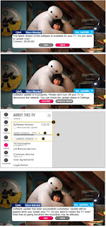
LG 32LK610BPUA, LG 32LK610BBUA LCD TVs – How to upgrade the software, fault checking method

  Software update procedure USB (1) Insert the USB memory Stick to the USB port (2) Automatically detect the SW Version and show the bel...