Used
ICs and semiconductors: TDA9210, TDA4856 (H.OSC), NT6828(OSD), 24C08(EEPROM),
KA2142(V-OUT), KTC5802 (H-Out transistor), CF1656-(FBT), H3842(SMPS Control
IC), SPP04N60S5( Power Switching FET), 1DWM240T---(System control)
Test
high voltage only by measuring it with an appropriate high voltage meter or
other voltage measuring device (DVM, FETVOM. etc.) equipped with a suitable
high voltage probe. Do not test high voltage by “drawing an arc” Discharge the picture tube anode only by: (a)
first connecting one end of an insulated clip lead to the degaussing or line
grounding system shield at the point where the picture tube socket ground lead
is connected, and then (b) touching the other end of the insulated clip lead to
the picture tube anode button, using an insulating handle to avoid personal
contact with high voltage.
This
color monitor automatically scans all horizontal frequencies from 30KHz to
70KHz, and all vertical frequencies from 50Hz to 160Hz. This color monitor
supports IBM PC, PC/XT, PC/AT, personal System/2 (PS/2), Apple Macintosh, and
compatible users crisp text and vivid color graphics display when using the
following graphics adapters : (VGA, 8514/A,
Super VGA, VESA and XGA and Apple Macintosh Video Card). And so, this
color monitor has a maximum horizontal resolution of 1280 dots and a maximum
vertical resolution of 1024 lines for superior clarity of display.
By accepting analog signal inputs which level is zero to 0.7 Volts. This color monitor can display and unlimited palette of colors depending on the graphics adapter and software being used.
By accepting analog signal inputs which level is zero to 0.7 Volts. This color monitor can display and unlimited palette of colors depending on the graphics adapter and software being used.

Adjustments [Pre-Adjustment]
B+
Adjustment
Adjust 50Vdc ± 0.1Vdc between D102 cathode and ground at 31.5KHz mode, varying
VR001.
Adjust 59Vdc ± 0.1Vdc between D510 cathode and ground at 31.5KHz mode, varying VR501.
Adjust 59Vdc ± 0.1Vdc between D510 cathode and ground at 31.5KHz mode, varying VR501.
Factory mode
Push
the menu button.
Push the menu button and plus control button (DN ) for 5 times in same time.
Push the menu button and plus control button (DN ) for 5 times in same time.
Setting the Controls
Set the value of items as following.
Contrast : Max.(OSD value up to MAX)
Brightness : Center(Set the OSD value to center)
2. H.size, V.size, H.center, V.center, Pin Balance, Pincushion, Trapezoid
Receive the cross hatch pattern of Factory preset mode.
H.size, V.size, H.center, V.center, Pin Balance, Pincushion, Trapezoid are adjusted at each mode.
In Factory, Auto Alignment was done at each mode. Therefore, Factory preset mode has it’s own value according to each control.
3. Focus
(a) Set brightness control to center and contrast control to MAX.
(b) Receive all “H” character pattern of 1024 X 768 (48KHz, 60Hz)
(c) Adjust the Focus control of FBT to obtain best Focus.
4. Geometric Distortion Adjustment.
(a) Receive the cross hatch pattern of factory preset mode.
(b) Pincushion, Trapezoid, Pin Balance are adjusted the best geometric status.
5. White Balance Adjustment
(a) Select 9300°K on the OSD Menu.
(b) Receive a full white pattern of 54KHz mode signal by using the signal generator.
(c) Set the brightness control to the maximum, the contrast control to the maximum.
(d) Cut off the FBT screen VR.
(e) Receive all the black patterns. The luminance of the screen should be 0.5~1.0 Ft-L by using Screen VR.
(f) Select the R-BIAS, G-BIAS and B-BIAS on the control menu and adjust the +/– key to get the color coordinates in x=0.281 ± 0.015, y=0.311± 0.015.
(g) Receive a full white pattern. Adjust the brightness value to the center.
(h) Select the R-GAIN and B-GAIN and adjust the +/– key to get the color coordinates in x=0.281 ± 0.015, y=0.311 ± 0.015.
(i) Adjust the ABL control to get the screen luminance to 30 Ft/L (a full white pattern over 30 Ft/L)
(j) Check if the x, y coordinates of color analyzer is in x=0.281±0.015, y=0.311±0.015.
If the color coordinates is out of range, adjust the R. G. B BIAS & GAIN to get the coordinates in x=0.281, y=0.311. Make sure that the coordinates is in range.
(k) Select 6550°K on the OSD Menu and set the color coordinates in x=0.313, y=0.329 at the maximum contrast control and center brightness control
(l) Check if a full white pattern is over 30Ft/L.
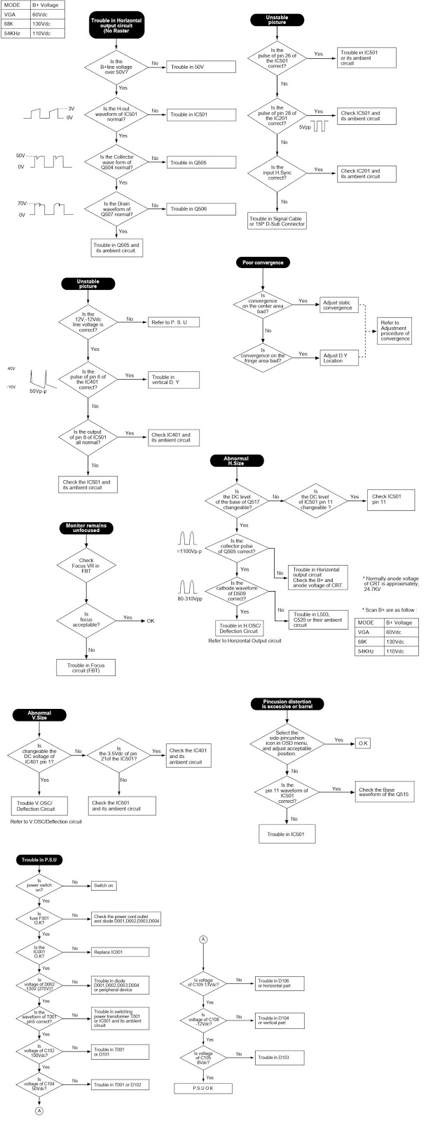
Troubleshooting table


PWB

Schematic


Static Convergence Adjustment
(a) Apply a magenta cross hatch pattern on display.
(b) Adjust the focus from the best over all focus on the display.
Also adjust the brightness to the desired condition.
(c) Vertical red and blue lines are converged by varying the angle between the two tabs of the 4-pole magnets.
(d) Horizontal red and blue lines are converged by varying the tabs together, keeping the angle between them constant.
(e) Apply a yellow cross hatch pattern on display.
(f) Vertical green and red lines are converged by barying the angle between the two tabs of the 6-pole magnets.
(g) Horizontal green and red lines are converged by varying the tabs together, keeping the angle between them constant.

