Wednesday, 1 August 2018

Apple TV 2nd generation DISASSEMBLING PROCEDURE


Apple TV – Apple TV 2nd generation - Disassembling procedure – How to removal the case – How to remove the logic board – How to remove the status LED
Use a spudger to pry the bottom cover off the Apple TV. It may be necessary to use two spudgers (one to hold it open while you pry with the other one)
Carefully remove the bottom cover from the unit
Remove the pink thermal pad. (I already removed mine) Remove the five philips #1 screws securing the heatsink and logic board to the upper casing.
Using a screwdriver (flathead) or a spudger, pull the power cable out of the logic board Now with a spudger or flathead screw driver, CAREFULLY remove the LED connector. Do this very carefully as this connector is extreme fragile, and easily damaged.
Use a flathead screwdriver or spudger to tilit the logic board to an angle so you can grab it with your hands Holding the logic board by it edges, lift it up slightly. And remove Thats all. The logic board has been removed. Just follow the steps (Step 1-5 in reverse to install the board)
The chip with the grease on is the Apple A4 chip. The thermal pad took the silkscreen off, so its hard to read. The The black ball surrounded by meta is the IR Remote sensor. In the third picture, the power connector and LED status connector are shown.
HDMI Port
Micro USB Port (used for diagnostics, and service)
Digital TOS Link out (Optical Out)
Gigabit Ethernet
The second picture shows the thermal pads (pinkish white edge stuff) this keeps the components of the logic board cool and happy.
LED status light replacing
The last remaining part in the Apple TV is the status LED. You can remove this part with your plastic spudger.
How to disassemble the 2nd generation Apple TV

Wednesday, 25 July 2018

TCL L32M61S3 – service mode and adjustments – working principle - Troubleshooting


TCL L32M61S3/L32E62S3/L32M71S3 (MS19) – 32 inch LCD TV – How to enter the service mode and service mode adjustments – working principle
This Chassis adopts Taiwan semiconductor plant MSTar’s integrative chip MST9E19A.It is a high performance and fully integrated IC for multi-function LCD monitor/TV with resolutions up to SXGA(1280x1024)/WXGA+(1440x900).It is configured with an integrated triple ADC-PLL, an integrated DVI/HDCP/HDMI receive a multi-standard TV video and audio decoder, a video de-interlacer, a scaling engine, the MStarACE-3 color engine an on-screen display controller, an 8-bit MCU, and a built-in output panel interface. To further reduce system costs, the MST9E19A also integrates intelligent power management control capability for green-mode requirement and spread-spectrum support for EMI management. Therefore, MS19 is a high cost performance Chassis.
Modes L32M61S3/L32E62SE/L32M71S3 just different in frame, their chassis includes hardware and software almost are same. To match the frame, just key board and remote control receive board have a little difference. Beside, the three modes TV support NTSC-M, PAL M and PAL N.
So that, the following alignment procedure adapt to the three modes above said.
 How to enter factory mode (service menu, service mode)
Method one, press MENU, input “1”,”9”,”5”,”0” in 3 seconds.
Method two, press “GO BACK” key directly. (Remark: it is must under conditions of, in factory mode, enter PRODUCTING, FACTORY HOT KEY set as ON.)
Factory menu explain
Enter factory menu, press the remote control’s UP, DOWN, LEFT, RIGHT key set or adjustment, press MENU key return parent menu, press MENU OR CLEAR KEY exit factory menu.
Aging
While TV need aging, pleas enter factory mode, set the WARM UP STATUS in producing as ON, then set power mode as ON in set up menu. If TV need standby aging, please set power mode as STB.
 ADC correct
This chassis can ADC correct when input YPBPR or PC signal resource. Enter factory mode, switch the source as YPBPR or PC, input 100% color bar signal, enter ADC ADJ item, choose AUTOTUNE item, press right key on remote control to start auto correct, when screen display OK 7 seconds later, it shows that ADC correct success. Then exit menu.
Remark: Before white balance adjustment, must do ADC correct OK in YPBPR and PC signal input.
White balance adjustment.
Normal, warm and cool three situations’ white balance color temperature value must obey the enterprise standard. Before adjust the white balance, please confirm if finished ADC correct under YPBPR and PC sources, in addition, the picture mode must be normal.
This chassis white balance adjustment must be adjusted in three signal sources.
(1)AV/TV/S-Video’s white balance adjust under AV signal source input. Signal should be NTSC-M eight-grey bar signal.
(2)YPBPR and HDMI white balance adjust under YPBPR signal source input. Signal must be 16-grey bar signal.
(3)PC white balance adjustment must be under PC signal input. The signal should be 16 grey bar signal.
Factory producing white balance adjustment according to the software interface agreement and working guide, setting relevant offsets to operate.
If it need human adjustment, please enter factory menu adjust WB items.
 leave factory setting.
Leave factory setting items have been listed in factory menu. Please set each character according to customers requirement. Or obey the default value. Before TV leave factory, please do “SHOP INIT DO”. Operate method is press left or right key on remote control to initial it. While OK display on screen, it finished the initial. Then turn TV off just OK..
Chassis MS19 circuitries include: tuner, decoder and scanner, audio amplifier, remote control receive, key input and power supply unit and so on. It adopted ICs as following, MST9E19A-LF 208PI, ISL8105IBZ, TDA7266 , TDA1308T/N2, TL431ACLP, M24C32, KD1084A-18.
I. Video signal input processing circuit.
Radio frequency signal from antenna or cable input tuner, after it processed, Pin17 of tuner output video signal, then input Pin49/50 of U8(MST9E19A).

AV signal input processing circuit.
AV1/AV3 through socket P14 input Pin45/Pin47 of U8, S-video input through socket P15 input Pin42/Pin43/Pin44 of U8. YCbCr Video Signal input through socket P16 input.
HDMI video signal input through socket P12 input Pin1-Pin15 of U8.
VGA input through socket P13 input Pin16-Pin28 of U8.
Audio signal input, the audio signal through antenna process and output from Pin7 of Tuner and input Pin54/Pin55 of U8.The AV1’s audio signal input Pin63/Pin64 of U8,AV2’s audio signal input Pin66/Pin67 of U8; AV3’s audio signal input Pin69 and Pin69 of U8.
All channels audio signal through inside circuitry process, output from Pin74/Pin75 of U8, send to audio amplifier U19( TDA7266SA) processing and driver speaker phonating.
Audio Amplifier and Mute Control
The audio signal after MST IC decoder and get out from Pin74/75 of MST IC, and through integral circuitry (R33,R38,C76 and R45,R50,C82) send to Pin4/12 of audio power amplifier U19 to drive speaker.
AV Output Audio Amplifier Section
The phone audio signal output from Pin71/Pin 71,through the integral circuitry R34/R36/C37 and R47/R51/C83 send to U16 and output from P17.
HDMI EDID Introduction
Extended display identification data (EDID) is a data structure provided by a computer display to describe its capabilities to a graphics card. It is what enables a modern personal computer to know what kind of monitor is connected. EDID is defined by a standard published by the Video Electronics Standards Association (VESA). The EDID includes manufacturer name, product type, phosphor or filter type, timings
supported by the display, display size, luminance data and (for digital displays only) pixel mapping data.
The channel for transmitting the EDID from the display to the graphics card is usually the I2C bus. The combination of EDID and I²C is called the Display Data Channel version 2, or DDC2. The 2 distinguishes it from VESA's original DDC, which used a different serial format.
Before DDC and EDID were defined, there was no standard way for a graphics card to know what kind of display device it was connected to. Some VGA connectors in personal computers provided a basic form of identification by connecting one, two or three pins to ground, but this coding was not standardized.
The EDID is often stored in the monitor in a memory device called a serial PROM (programmable read-only memory) or EEPROM (electrically erasable PROM) that is compatible with the I²C bus.
HDCP Section
High-bandwidth Digital Content Protection (HDCP) is a form of Digital Rights Management (DRM) developed by Intel Corporation to control digital audio and video content as it travels across Digital Visual Interface (DVI) or High-Definition Multimedia Interface (HDMI) connections. The specification is proprietary, and creating an implementation of HDCP requires a license .HDCP is licensed by Digital
Content Protection, a subsidiary of Intel. In addition to paying fees, licensees agree to limit the capabilities of their products. For example, high-definition digital video content must be restricted to DVD quality on non-HDCP compliant video outputs when requested by the source. DVD-Audio content is restricted to DAT quality on non-HDCP digital audio outputs (analog audio outputs have no quality limits).
Licensees cannot allow their devices to make copies of content, and must design their products in ways that "effectively frustrate attempts to defeat the content protection requirements."
Each HDCP capable device has a unique set of keys; there are 40 keys, each 56 bits long. These keys are confidential and failure to keep them secret may be seen as a violation of the license agreement. For each set of keys a special key called a KSV (Key Selection Vector) is rated. Each KSV has exactly 20 bits set to 0 and 20 bits set to 1.
During the authentication process, both parties exchange their KSVs. Then each device adds (without overflow) its own secret keys together according to a KSV received from another device. If a particular bit in the vector is set to 1, then the corresponding secret key is used in the addition, otherwise it is ignored. Keys and KSVs are generated in such a way that during this process both devices get the same 56 bit number as a result.
That number is later used in the encryption process. As result that, this chassis adopts 24C04 to storage KSV and license makes digital signal resource output.
EEPROM for Software
It adopts Winbond company’s W25X40 flash which has 4M-bit/526 bytes and 2048pages.It is used for storage the main system software. The devices operate on a single 2.7V to 3.6V power supply with current consumption as low as 5mA active and 1uA for power-down.
EEPROM for User Information
It adopts I2C compatible electrically erasable programmable memory (EEPROM) devices are organized as 4096x8 bits(32k).This is a two-wire series interface that uses a bi-directional data bus and serial clock. It is used for storage user’s information, such as channel search and timer on and off, and picture standard and other information what user’s easy to change by local key board and remote control.
Panel ON/OFF Control Section
While the TV is turn on, the TV is standby situation. While command turn on is send out, 5v voltage will through regulator and equal get 3.3V voltage or 1.8V voltage supply for U8. After reset and crystal Y1 working, the main system software will be loaded, the panel –ON/OFF command will be sent out, makes the dual-MOSFET U3 turn on and send V/12V/3.3V voltage to the panel.
Panel ON/OFF Control Section
While the TV is turn on, the TV is standby situation. While command turn on is send out, 5v voltage will through regulator and equal get 3.3V voltage or 1.8V voltage supply for U8. After reset and crystal Y1 working, the main system software will be loaded, the panel –ON/OFF command will be sent out, makes the dual-MOSFET U3 turn on and send V/12V/3.3V voltage to the panel.
Power Logic Sequence
While the power cord plug in, the TV is in standby situation, power supply unit provide 5Vstb 200mA for load. There is no 12v amplifier power supply and 24V inverter voltage supply. The 5Vstb through D7 and regulator U5 get 3.3VA supply for IC (MST19E),the another path of circuit is 5Vstb through regulator U6 get 3.3V then regulated by U7(regulator) get 1.8V supply for U8(MST19E),drive the LED lighting, and standby circuitry working, and CPU controlling, reset circuitry,crystal.So that it makes the CPU can receive and send kinds of command. while there is turn on command(low level) send out from Pin150 of U8(MST19E),power supply unit provide 12V and 24V voltage.12V voltage supply for U1/U2,change to 5V voltage, regulate by U6, change to 3.3V supply for U8 others parties. 24V voltage supply for inverter board of Panel.

Troubleshooting

Defective picture
No picture
Not working
Picture OK but No sound
                               

Friday, 20 July 2018

AOC LE32D1440/20- AOC LE39D1440/20 – SMPS schematic, troubleshooting and firmware update


Adjustment
White Balance Adjustment
In Component signal mode, Signal generator will select Tim 314, Pattern 141(80% White);
Press "Menu +1+9+9+9+ Back" into the factory mode.
Move the cursor to Current Source and choose component; Move the cursor to Color temp and choose color temp(Cool, Normal, Warm), Move the cursor to the Gain and adjust RGB parameters to make the color temperature value within the cool color temperature specifications(Specifications in the following table) (NOTE: What we need is the Gain after the Color temp )
Firmware Instruction
Change the software file name to “install.img”.
Prepare a USB memory. Copy the file “install.img” from your computer to the USB memory root directory, and remove it from computer’s USB port.
F/W Upgrade
Insert USB flash disk into TV’S USB
AC on the TV, the indicator light will shine after about tens of seconds, and the software will update automatically.
TV will auto restart after update the software.
After restart, press “menu+1999+back” keys in remote control into the factory menu. Check the version of MCU, and restart, software update is completed.
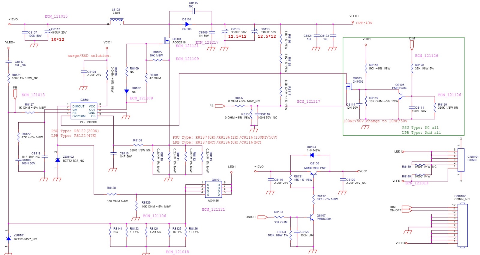
SMPS schematic
Troubleshooting

Wednesday, 18 July 2018

Philips PM2502 Analogue Multimeter and Hung Chang 303TR Digital Multimeter circuit diagram (Schematic)

Philips PM2502 Analogue Multimeter Circuit diagram and specifications
HUNG CHANG 303TR Digital multimenter circuit diagram
 Ex-Or gate truth table

Sunday, 15 July 2018

HP OMEN 15 - Notebook – Disassembling procedure


HP OMEN 15 - Notebook – Disassembling procedure – How to remove the Battery – How to remove the case – How to remove the SSD
How to remove Bottom cover
Before replacing the bottom cover, follow these steps:
1. Turn off the computer. If you are unsure whether the computer is off or in Hibernation, turn the computer on, and then shut it down through the operating system.
2. Disconnect the power from the computer by unplugging the power cord from the computer.
3. Disconnect all external devices from the computer.
Remove the bottom cover:
1. Close and position the computer upside down with the front toward you.
2. Pry up to remove the rubber strips from the bottom of the computer
3. Remove the 11 Phillips PM2.0×5.0 screws that secure the bottom cover to the computer
4. Lift the bottom cover off the computer.
How to Disconnect the battery
Before disconnecting the battery, follow these steps:
1. Turn off the computer. If you are unsure whether the computer is off or in Hibernation, turn the computer on, and then shut it down through the operating system.
2. Disconnect the power from the computer by unplugging the power cord from the computer.
3. Disconnect all external devices from the computer.
4. Remove the bottom cover
Disconnect the battery:
 Pull to disconnect the battery cable from the system board connector.
How to remove WLAN module
Before replacing the WLAN module, follow these steps:
1. Turn off the computer. If you are unsure whether the computer is off or in Hibernation, turn the computer on, and then shut it down through the operating system.
2. Disconnect the power from the computer by unplugging the power cord from the computer.
3. Disconnect all external devices from the computer.
4. Remove the bottom cover
5. Disconnect the battery 
Remove the WLAN module:
1. Disconnect the WLAN antenna cables (1) from the terminals on the WLAN module.
2. Remove the Phillips PM2.0×3.0 screw (2) that secures the WLAN module to the system board.
3. Remove the WLAN module (3) by pulling the module away from the slot.
How to remove Solid-state drive
Before removing the solid-state drive, follow these steps:
1. Turn off the computer. If you are unsure whether the computer is off or in Hibernation, turn the computer on, and then shut it down through the operating system.
2. Disconnect the power from the computer by unplugging the power cord from the computer.
3. Disconnect all external devices from the computer.
4. Remove the bottom cover
5. Disconnect the battery
Remove the solid-state drive:
1. Remove the Phillips PM2.0×3.5 screw (1) that secures the solid-state drive to the system board.
2. Remove the solid-state drive (2) by pulling the drive away from the slot at an angle.
How to remove Battery
Before replacing the battery, follow these steps:
1. Turn off the computer. If you are unsure whether the computer is off or in Hibernation, turn the computer on, and then shut it down through the operating system.
2. Disconnect the power from the computer by unplugging the power cord from the computer.
3. Disconnect all external devices from the computer.
4. Remove the bottom cover
Remove the battery:
1. Disconnect the battery cable from the system board (1) .
2. Remove the four Phillips PM2.0×4.0 screws (2) that secure the battery to the computer.
3. Lift the battery (3) from the computer.
How to remove TouchPad
Before replacing the TouchPad, follow these steps:
1. Turn off the computer. If you are unsure whether the computer is off or in Hibernation, turn the computer on, and then shut it down through the operating system.
2. Disconnect the power from the computer by unplugging the power cord from the computer.
3. Disconnect all external devices from the computer.
4. Remove the bottom cover
5. Remove the battery
Remove the TouchPad:
1. Disconnect the TouchPad cable from the system board (1).
2. Remove the Mylar from atop the middle screw of the touchpad (2).
3. Remove the Æ­ve Phillips PM1.5×2.0 broad head screws (3) that secure the TouchPad to the computer.
4. Remove the TouchPad (4).

Saturday, 14 July 2018

How to replace the battery of Apple iPhone 6 Plus


Power off your iPhone before beginning disassembly. 
Remove the two 3.6 mm Pentalobe screws next to the Lightning connector.
The next two steps demonstrate using the iSclack, a great tool for safely opening the iPhone 6 Plus that we recommend for anyone doing more than one repair. 
 If the plastic depth gauge is attached at the center of the iSclack, remove it now—it's not needed for larger phones like the iPhone 6 Plus.
Close the handle on the iSclack, opening the suction cup jaws.
Place the bottom of your iPhone in between the suction cups.
Position the iSclack's upper suction cup against the display, near the home button. Open the handles to close the jaws of the iSclack. Center the suction cups and press them firmly onto the top and bottom of the iPhone.
Hold onto your iPhone securely and close the handle of the iSclack to separate the suction cups, pulling the front panel up from the rear case. The iSclack is designed to safely open your iPhone enough to separate the pieces, but not enough to damage any of the display cables. Peel the two suction cups off your iPhone.
If you don't have an iSclack, use a single suction cup to lift the front panel: Press a suction cup onto the screen, just above the home button.
 Be sure the cup is pressed securely onto the screen to get a tight seal.
If you don't have an iSclack, use a single suction cup to lift the front panel: Press a suction cup onto the screen, just above the home button.
Be sure the cup is pressed securely onto the screen to get a tight seal.
Pull the plastic nub to release the vacuum seal on the suction cup. Remove the suction cup from the display assembly.
Pull the home button end of the front panel assembly away from the rear case, using the top of the phone as a hinge. During the next few steps, until you remove the front panel assembly, keep it supported at a 90 degree angle in relation to the rear case
Several clips along the top edge of the front panel form a partial hinge, allowing the front panel assembly to swing open like a book. During reassembly, align the clips just below the top edge of the rear case. Then, slide the front panel upward until its top edge is flush with that of the rear case.
While holding the front panel open at about a 90 degree angle, remove the following screws securing the front panel assembly cable bracket:
Three 1.2 mm Phillips #00 screws
One 1.5 mm Phillips #00 screw
One 2.9 mm Phillips #00 screw
Remove the front panel assembly cable bracket from the logic board.
In the next four steps, take care to pry up only on the cable connectors, and not on their sockets on the logic board. While still supporting the front panel, use a plastic opening tool to disconnect the front facing camera and earpiece speaker cable connector.
Use a plastic opening tool to disconnect the home button cable connector.
Use a plastic opening tool to disconnect the display data cable connector. When reassembling your phone, the display data cable may pop off the connector. This can result in white lines or a blank screen when powering your phone back on. If that happens, simply reconnect the cable and power cycle your phone. The best way to power cycle your phone is to disconnect and reconnect the battery connector.
Finally, use a plastic opening tool to disconnect the digitizer cable connector.
Remove the front panel assembly rom the rear case.
Remove the following screws from the battery connector bracket:
One 2.3 mm Phillips #00 screw
One 3.1 mm Phillips #00 screw
Remove the metal battery connector bracket from the iPhone.
Use a plastic opening tool to gently pry the battery connector up from its socket on the logic board. Take care to only pry up on the battery connector, and not the socket on the logic board. If you pry up on the logic board socket, you may break the connector entirely.
Peel back the first battery adhesive tab from the bottom right edge of the battery. Use your fingers or blunt tweezers. Be extra careful when working near the battery; puncturing a lithium-ion battery can release dangerous chemicals and cause a fire.
Gently pull the battery adhesive tab away from the battery, toward the bottom of the iPhone.
To avoid tearing the adhesive strip, be careful not to pull against the battery or lower components.
Continue pulling, allowing the strip to slowly slip out from between the battery and the rear case. When you feel increased resistance from the strip, stop pulling and continue with the next step.
If the battery adhesive tabs break during the removal process, use your fingers or blunt tweezers to retrieve the remaining length of adhesive, and continue pulling.
When you feel increased resistance from the adhesive strip, pull it gently around the lower right corner of the battery. Avoid snagging the adhesive strip on the corner of the battery or the strip may tear or break.
Continue pulling the adhesive tab upward and away from the right edge of the battery, allowing it to slowly slide out from between the battery and the rear case, until the strip comes free from the iPhone. Don't allow the adhesive strip to snag on the battery connector, or it may tear or break off.
Peel back the second battery adhesive tab from the bottom left edge of the battery. Again, gently pull the battery adhesive tab upward and away from the battery, allowing the adhesive strip to slowly slide out from between the battery and the rear case. Continue pulling the adhesive tab until you feel increased resistance, and then stop.
When you feel increased resistance from the adhesive strip, pull it gently around the lower left corner of the battery. Don't allow the adhesive strip to snag on the corner of the battery, or it may tear or break off. Continue pulling the adhesive tab upward and away from the left edge of the battery, allowing it to slowly slide out from between the battery and the rear case, until the strip comes free from the iPhone.
Peel back the final battery adhesive tab from the bottom edge of the battery. Gently pull the battery adhesive tab upward and away from the battery, allowing the adhesive strip to slowly slide out from between the battery and the rear case.
Continue pulling until the final strip comes free from the iPhone.
Flip the iPhone back over and insert a plastic card between the left side of the battery and the rear case. Be careful to keep the card as flat as possible to avoid bending the battery, which may damage it and cause it to release dangerous chemicals. Press the card in farther to break up the adhesive behind the battery.
Remove the battery from the iPhone.

Friday, 13 July 2018

Acer Aspire E15 - Troubleshooting Hardware and software problems


Acer Aspire E15:  TROUBLESHOOTING 
Sound Problems
Perform the following, one at a time.
1. Boot the computer.
2. Navigate to Start > Control Panel > System and Maintenance > System > Device Manager. Check the Device Manager to determine that:
#The device is properly installed
# There are no red Xs or yellow exclamation marks
# There are no device conflicts
# No hardware is listed under Other Devices
3. If updated recently, roll back the audio driver to the previous version.
4. Remove and reinstall the audio driver.
5. Make sure that all volume controls are set mid range:
# Click the volume icon on the taskbar
# Drag the slider to 50. Confirm that the volume is not muted.
# Click Mixer to verify that other audio applications are set to 50 and not muted.
6. Navigate to Start´ Control Panel´ Hardware and Sound´ Sound. Confirm that Speakers are selected as the default audio device (green check mark).
NOTE:If Speakers does not show, right-click on the Playback tab and select Show
Disabled Devices (clear by default).
7. Select Speakers and click Configure to start Speaker Setup. Follow the on-screen prompts to configure the speakers.
8. Remove any recently installed hardware or software.
9. Restore system and file settings from a known good date using System Restore.
10. If the issue is remains, repeat step 9, selecting an earlier time and date.
11. Reinstall the Operating System.
Microphone Failure
1. Check that the microphone is enabled. Navigate to Start > Control Panel > Hardware and Sound > Sound and select the Recording tab.
2. Right click on the Recording tab and select Show Disabled Devices (clear by default). The microphone appears on the Recording tab.
3. Right click on the microphone and select Enable.
4. Select the microphone then click Properties. Select the Levels tab.
5. Increase the volume to the maximum setting and click OK.
6. Test the microphone hardware:
# Select the microphone and click Configure.
# Select Set up microphone.
# Select the microphone type from the list and click Next.
# Follow the on-screen prompts to complete the test.

HDD Not Operating Correctly 
If the HDD fails to operate correctly, perform the following:
1. Disconnect all external devices.
2. Run a complete virus scan using up-to-date software to confirm the computer is virus free.
3. Run the Windows Vista Startup Repair Utility:
a. Insert the Windows Vista Operating System DVD in the ODD and restart the computer.
b. When prompted, press any key to start to the operating system DVD.
c. When the Install Windows screen appears, click Next.
d. Select Repair your computer.
e. When the System Recovery Options screen appears, click Next.
f. Select the appropriate operating system, and click Next.
NOTE: Click Load Drivers if controller drives are required.
g. Select Startup Repair.
NOTE: Startup Repair attempts to locate and resolve issues with the computer.
h. When complete, click Finish.
If an issue is discovered, follow the on-screen information to resolve the problem.
1. Run the Windows Memory Diagnostic Tool. For more information see Windows Help and Support.
2. Restart the computer and press F2 to enter the BIOS Utility. Check the BIOS settings are correct and that CD/DVD drive is set as the first boot device on the Boot menu.
3. Confirm all cables and jumpers on the HDD and ODD are set correctly.
4. Remove any recently added hardware and associated software.
5. Run the Windows Disk Defragmenter. For more information see Windows Help and Support.
6. Run Windows Check Disk by entering chkdsk /r from a command prompt. For more information see Windows Help and Support.
7. Restore system and file settings from a known good date using System Restore.
8. If the issue is not fixed, repeat the preceding steps and select an earlier time and date.
9. Replace the HDD.
Computer Shuts Down Intermittently
If the system powers off at intervals, perform the following.
1. Makes sure the power cable is properly connected to the computer and the electrical outlet.
2. Remove all extension cables between the computer and the outlet.
3. Remove all surge protectors between the computer and the electrical outlet. Plug the computer directly into a known serviceable electrical outlet.
4. Disconnect the power and open the casing to check the Thermal Unit and fan airways are free of obstructions.
5. Remove all external and non-essential hardware connected to the computer that are not necessary to boot the computer to the failure point.
6. Remove any recently installed software.
No POST or Video
If the POST or video does not appear, perform the following, one at a time.
1. Make sure that internal display is selected. Switching between internal and external by pressing Fn+F5. Reference Product pages for specific model procedures.
2. Make sure the computer has power by checking for one of the following:
# Fans start up 3 Status LEDs illuminate
3. Drain stored power by removing the power cable and battery. Hold the power button for 10 seconds.
4. Connect the power and reboot the computer.
5. Connect an external monitor to the computer and switch between the internal display and the external display is by pressing Fn+F5.
6. If the POST or video appears on the external display only.
7. Disconnect power and all external devices including port replicators or docking stations. Remove any memory cards and CD/DVD discs.
8. Start the computer. If the computer boots correctly, add the devices one by one until the failure point is discovered.
9. Reseat the memory modules.
10. Remove the drives
Abnormal Video
If the video appears abnormal, perform the following, one at a time.
1. Boot the computer.
# If permanent vertical/horizontal lines or dark spots appear in the same location, the LCD is faulty and should be replaced.
# If extensive pixel damage is present (different colored spots in the same locations on
the screen), the LCD is faulty and should be replaced
NOTE:Make sure that the computer is not running on battery alone as this may reduce display brightness.
2. Adjust the brightness to its highest level. Refer to the User Manual for instructions on adjusting the settings. If the display is too dim at the highest brightness setting, the LCD is faulty and should be replaced.
3. Check the display resolution is correctly configured:
# Minimize or close all Windows.
# If display size is only abnormal in an application, check the view settings and control/mouse wheel zoom feature in the application.
# If desktop display resolution is not normal, right-click on the desktop and select
Personalize Display Settings.
# Click and drag the Resolution slider to the desired resolution.
# Click Apply and check the display. Readjust if necessary.
4. Roll back the video driver to the previous version if updated.
5. Remove and reinstall the video driver.
6. Check the Device Manager to determine that:
# The device is properly installed. There are no red Xs or yellow exclamation marks
# There are no device conflicts
# No hardware is listed under Other Devices.
Intermittent Problems 
Intermittent system hang problems can be caused by a variety of reasons that have nothing to do with a hardware defect, such as: cosmic radiation, electrostatic discharge, or software errors. FRU replacement should be considered only when a recurring problem exists.
When analyzing an intermittent problem, perform the following:
1. Run the advanced diagnostic test for the system board in loop mode at least 10 times.
2. If no error is detected, do not replace any FRU.
3. If an error is detected, replace the FRU. Rerun the test to verify that there are no more errors.
Undetermined Problems
The diagnostic problems does not identify which adapter or device failed, which installed devices are incorrect, whether a short circuit is suspected, or whether the system is inoperative.
Perform the following procedures to isolate the failing FRU (do not isolate non-defective FRU).
NOTE: Verify that all attached devices are supported by the computer.
NOTE: Verify that the power supply being used at the time of the failure is operating correctly.
1. Remove power from the computer.
2. Visually check them for damage. If any problems are found, replace the FRU.
3. Remove or disconnect all of the following devices:
# Non-Acer devices
# Printer, mouse, and other external devices
# Battery pack
# Hard disk drive
# DIMM
# CD-ROM/Diskette drive Module
# PC Cards
4. Apply power to the computer.
5. Determine if the problem has changed.
6. If the problem does not recur, connect the removed devices one at a time until failing FRU is found.
7. If the problem remains, replace the following FRUs one at a time. Do not replace a non-defective FRU:
# System board
# LCD assembly

LG 32LK610BPUA, LG 32LK610BBUA LCD TVs – How to upgrade the software, fault checking method

  Software update procedure USB (1) Insert the USB memory Stick to the USB port (2) Automatically detect the SW Version and show the bel...