Friday, 24 April 2020

SONY HD CAMCORDER PMW EX3 How to enter the Service mode, White balance adjustments, Black shade adjustment, firmware update, resetting procedure


SONY PMW-EX3  SERVICE Menu Description
Basic Menu Operation
Press the MENU button to enter the menu mode.
Press the PICTURE PROFILE button, the MENU button, or the STATUS button while the menu is displayed to close the menu display. The menu display is closed when the power is turned off.
1. Press the MENU button. The system enters the menu mode.
2. Press the arrow key to move the cursor to the desired setting item and press the SEL/SET button.
Exiting the Menu Mode
Press the MENU button again.
The system exits the menu mode to return to the normal camera mode.
SERVICE Menu Structure
The SERVICE menu consists of the three SERVICE dedicated menus and the six ordinary SETUP menus for a total of nine menus.
MAINTENANCE  - Adjustment of parameters
RPN CORRECT -  Operations regarding the RPN correction
INFORMATION - Information display on the particular PMW-EX3 and self-diagnostics.
The MAINTENANCE menu and the RPN CORRECT menu can be operated in the CAMERA mode only.
Displaying the SERVICE Menu
# To display the SERVICE menu, press the CANCEL button, the MENU button, and the JOG dial at the same time.
Pressing the MENU button again closes the SERVICE menu display.
# Once the SERVICE menu has been displayed, simply pressing the MENU button displays the SERVICE menu instead of the normal SETUP menu unless the power is turned off.
SERVICE Menu Description
MAINTENANCE Menu
The MAINTENANCE menu enables setting for image device and setting parameters that must be set uniquely to each PMW-EX3 for correction of non-uniformity between the respective lens characteristics.
1. Test Saw setting
# Test Saw setting enables the operator to select the Test Saw signal instead of the imager output signal when recording or outputting images in CAMERA mode.
2. Executing Auto Black Balance
# Executing the Auto Black Balance triggers the auto black balance adjustment (automatic black level adjustment).
# When the Auto Black Balance menu is selected, the Execute and Cancel choices appear. Selecting Execute starts Auto Black Balance.
# When the Auto Black Balance is executed, the execute RPN automatic detection.
Auto Black Balance cannot be executed from the SERVICE menu under the following settings. Change the settings to execute Auto Black Balance.
# When Video Format other than HQ 1080/60i or HQ 1080/50i is selected.
# When electronic shutter is operating in the SLS mode.
# When the EX Slow Shutter is set to ON.
Black Shading Adjustment
All of the Black Shading correction values have been set to ±0 when shipped from the factory.
(When the Black Shading correction is executed, it results in height difference of black level at the boundary areas between the corrected areas). Do not change the Black Shading correction values to any values other than ±0 unless it is necessary.
# The Black Shading menu enables the H Saw correction level adjustment, V Saw correction level adjustment and parabola correction level adjustment.
# The Black Shading setting menu can be used to turn Black Shading correction On or Off. The Black Shading setting is turned On automatically when the power is turned On.
# The Channel Select menu enables selection of the channel (G-ch or B-ch or R-ch) to execute the H Saw, H Para, V Saw, and V Para black shading adjustments on.
# When the Channel Select menu selects any other channel, the displays of the H Saw, H Para, V Saw, and V Para setup values are changed to the current setup values of the channel selected by the Channel Select menu. The changes are reflected on the H Saw, H Para, V Saw, and V Para setup values.
# The H Saw menu enables the horizontal Saw black shading correction (linear increase and decrease) level.
# The H Para menu enables the horizontal Parabola black shading correction (black level correction at the horizontal center with respect to both ends) level.
# The V Saw menu enables the vertical Saw black shading correction (linear increase and decrease) level.
# The V Para menu enables the vertical Parabola black shading correction (black level correction at the vertical center with respect to both ends) level.
# The Auto BLK Shad menu enables the auto black shading correction (automatic optimization of the respective correction values of the black shading correction).
# When Auto BLK Shad menu is selected, the Execute and Cancel choices appear.
Selecting Execute starts Auto Black Shading.
Black shading adjustment method
Preparation
3 Connect an HD waveform monitor to the SDI OUT terminal.
3 HD waveform monitor setting: RGB mode
3 Lens iris > CLOSE
Adjustment Procedure
# Adjust GAIN and BLK level for easy viewing to observe.
# Adjust H Saw, H Para, V Saw and V Para for the respective channels of G-ch, B-ch and R-ch until waveform on the waveform monitor becomes flat.
Fig-1White Shading Adjustment
The White Shading menu enables the adjustment of the horizontal and vertical Saw correction level and parabola correction level.
The White Shading adjustment cannot be executed for the correct adjustment values if the object pattern has non-uniformity or if other conditions such as lens iris setting and zoom setting are not correctly satisfied. .
# Use a full white pattern for the White Shading adjustment having uniform brightness over the entire area.
# If a full white pattern having uniform brightness over the entire area is not available, do not execute the G-channel White Balance adjustment. Instead of it, execute the White Balance adjustment in the way of aligning the Rchannel waveform and the B-channel waveform to the waveform of G-channel.
# The White Shading setting menu can be used to turn White Shading correction On or Off. The White Shading setting is turned On automatically when the power is turned On.
# The Channel Select menu enables selection of the channel (G-ch or B-ch or R-ch) to execute the H Saw, H Para, V Saw, and V Para white shading adjustments on.
# When the Channel Select menu selects any other channel, the displays of the H Saw, H Para, V Saw, and V Para setup values are changed to the current setup values of the channel selected by the Channel Select menu. The changes are reflected on the H Saw, H Para, V Saw, and V Para setup values.
# The H Saw menu enables the horizontal Saw white shading correction (linear increase and decrease) level.
# The H Para menu enables the horizontal Parabola white shading correction (sensitivity correction at the horizontal center with respect to both ends) level.
# The V Saw menu enables the vertical Saw black shading correction (linear increase and decrease) level.
# The V Para menu enables the vertical Parabola white shading correction (sensitivity correction at the vertical center with respect to both ends) level.
White shading adjustment method
Preparation
# Connect an HD waveform monitor to the SDI OUT terminal.
# HD waveform monitor setting: RGB mode
# Focus > infinity
# Shoot an all white pattern over the entire frame of monitor screen.
Adjustment Procedure
# Adjust lens iris until white level becomes approximately 80%. If the lens iris value is larger than F5.6, adjust the incoming light intensity by using electronic shutter for the lens iris setting of smaller than F5.6.
# Adjust H Saw, H Para, V Saw and V Para for the respective channels of G-ch, B-ch and R-ch until waveform on the waveform monitor becomes flat.
Flare Adjustment
The Flare Adjustment menu enables flare compensation for the respective channels of G-channel, B-channel and Rchannel.
Flare adjustment method
Preparation
# Connect an HD waveform monitor to the SDI OUT terminal.
# HD waveform monitor setting: RGB mode
# Shoot a gray-scale chart to fill the entire screen of the picture frame and execute the white balance.
# Set the Knee to the Auto or Off.
Adjustment Procedure
# Adjust lens iris until white level becomes approximately 100%. After that, open the lens iris by two stops.
# Select waveform of the signal at the center of grayscale signal on a waveform monitor.
Adjust R Flare, G Flare and B Flare until the black levels on both sides of the center white in all of the R, G and B channels to a unity level. (Align black level all channels to that of the channel having the lowest black level.)
The flare adjustment can be performed only when there is a correct grayscale chart.
# When there is no correct grayscale chart, adjust the values of R Flare, G Flare and B Flare to ±0.
Firmware Upgrade
Upgrade the firmware for the PMW-EX1 through a USB connection to a computer. For detailed information about the upgrade procedure, check the readme file that comes with the upgrade software.
Firmware Upgrade Procedure
Download the software for the new firmware upgrade onto the computer before starting these operations.
1. Check that the power switch on the PMW-EX3 is turned OFF.
2. Remove the pad sub assembly and pad center cover.
3. Use the USB connector that comes with the PMW-EX3 to connect the computer and the USB maintenance connector.
4. Switch the power switch to CAMERA and turn the power ON.
5. Run the software for the firmware upgrade on the computer.
6. When the upgrade is complete, turn OFF the power and remove the USB cable.
7. Attach the pad sub assembly and pad center cover. When the PMW-EX3 is connected to the computer for the first time, the driver software will need to be installed into the computer. For more details, check the readme file that comes with the upgrade software.
Lithium Battery Replacement Procedures
1. Loosen the screw, and remove the button battery lid.
2. Remove the lithium battery.
3. Reinstall the lithium battery by reversing the steps of removal.
Executing Reset
# The Reset menu enables the user to delete the RPN correction point data that is registered by Auto Detect and Auto Black Balance after the equipment is shipped from the factory.
# The RPN data that is registered at the factory and the RPN data is manually registered cannot be deleted by the Reset.
# When the Reset menu is selected, the Execute and Cancel choices appear. In addition, selecting Execute starts reset of RPN.

PANASONIC AG AC7P Memory Card Camera Recorder How to enter the Service mode factory reset How to replace the lithium battery, service position


PANASONIC AG-AC7P
Service Mode
1. Indication method of the service menu
Set the mode switch “Motion Picture Recording” mode.
2. Turn the power on, and then while keep pressing the “Zoom lever” to W side, “Focus” switch and “Menu” button for more than 3 seconds until the top screen of the Service Mode Menu being displayed.
How to Replace the Lithium Battery
Replacement Procedure
1. Remove the Side-R Int P.C.B.. (Refer to Disassembly Procedures.)
2. Remove the Lithium battery (Ref. No. “B6701” at foil side of Side-R Int P.C.B.) and then replace it into new one.
CAUTION:
The battery used in this device may present a risk of fire or chemical burn if mistreated.
Do not recharge, disassemble, heat above 100°C (212°F), or incinerate.
Replace battery with Panasonic part number ML-614S/ZTK only. Use of another battery may present a risk of fire or explosion.
Dispose of used battery promptly. Keep away from children.
Do not disassemble and do not dispose of in fire.
Do not using service mode except above table of Service Menu.
3. End method of the top screen of the service menu. Push the “Menu” button to end the service mode, and then POWER OFF.
Lock Search History Indication
Touch the [ 4 ] of LCD, select Lock search history indication.
Indication contents
• Lock search history indication.
Display the camera system error cord for three histories saved in EEPROM.
• The error cord contents which are displayed.
Power ON Self Check Result Display
Touch the [ 5 ] of LCD, select Power ON self check result display.
Indication contents
• Power ON self check result display.
Function to diagnose correct function of the device and interface between devices result display.
Display the following communication test result.
- CAM-PWR : Communication test between IC2006 to IC301.
- CAM-UNI : Communication test between IC3401 to IC301.
Display other than “OK” are abnormalities of each lines.
Cutting of battery connection or AC power supply connection to end the service mode.
Service Position
This Service Position is used for checking and replacing parts. (Extension cable is not use.)
Factory Setting
How To Turn On The Factory Settings
1. Set the mode switch “Motion Picture Recording” mode.
2. Turn the power on, and then while keep pressing the “Zoom lever” to W side, “Focus” switch and “Menu” button for more than3 seconds until the top screen of the Service Mode Menu being displayed.
3. Touch the [ 1 ] of LCD.
4. Touch the [ YES ] of LCD.
5. After few seconds “END” is displayed on LCD monitor. Cutting of battery connection or AC power supply connection as a completion of the “FACTORY SETTINGS”.
What Is The Factory Settings
The factory settings clean up and/or refresh the following settings.
1. MENU, MODE, ADJUSTMENT VALUE.
2. SD card format.
3. Reset the folder number and file number of still pictures. (Setting the folder number is 100, and file number is 0.)
4. Clear the mechanism lock information.
5. Clear the service mode information contents.
6. Initialize the VIERA Link Physical Address.

Thursday, 2 April 2020

PT-LC150 Panasonic LCD Projector – How to enter the service mode, service mode and circuit adjustment details, Initialize the projector


Applicable to  Panasonic LCD Projector PT-LC50U PAL/SECAM/NTSC/PAL-M/PAL-N/NTSC4.43, PT-LC50U, PT-LC50E, PT-LC150 
Projector lamp
130 W UHM Lamp
LCD panels
0.7” Poly silicon LCD panel × 3,
RGB shutter method, using Translucent TN crystal panels.
How to display Lamp operation time (Service Mode)
1. Under the condition of the Lamp Cover SW “ON”, plug in the Power Cord.
2. Input a Signal.
3. Connect a jumper wire between TP2007 and TP2008 on Main C.B.A. for over 5 seconds as shown.
4. Lamp operation time will be displayed as shown.
5. Connect a jumper wire between TP2007 and TP2008 for over 5 seconds again or press MENU button on remote control in order to release from service mode.
[After replacing Main C.B.A., memory data such as history of lamp operation time will be reset. However, it can be remained by installing EEPROM IC (IC2006) to replaced Main C.B.A. from original Main C.B.A]
How to initialize EEPROM IC
If EEPROM IC (IC2006) on Main C.B.A. are replaced:
After replacing EEPROM IC (IC2006), be sure to perform each of following steps in the order presented.
1. Connect a jumper wire between TP2017 and TP2018 on Main C.B.A. for over 5 seconds to set to factory set mode. Then, remove the jumper wire.
2. “FACTORY” appears on screen.
3. Connect a jumper wire between TP2017 and TP2018 again for over 5 seconds to initialize EEPROM IC. Then, remove the jumper wire.
4. “SELF CHECK” appears on screen.
5. Remove jumper wires and “MEMORY OK” appears on screen.
6. Perform adjustments;
7. After completing all adjustments, press the MENU button to memorize adjustment data in EEPROM IC and release from the Factory Adjust mode. Otherwise, adjustment data will be cancelled.
[When initializing EEPROM IC, memory data such as history of lamp operation time and adjustment data will be reset.]
Lamp replacement procedure
Because of possibility of injury, strictly follow the replacement procedure below.
1. After the cooling fan has stopped, and STANDBY(R) ON(G) indicator turns solid red, unplug the power cord.
Note: Please wait more than one hour for lamp replacement.
[ If you need to replace the lamp more urgently ]
- The LCD Projector has a forced cooling feature. After the POWER switch is turned OFF, and sometime during about the first minute of the normal cooling fan operation, press MENU for 5 seconds. The cooling fan will change to high speed forabout 10 minutes. (The "C-d" STATUS CODE will be displayed.)
Loosen 2 fixing screws of lamp cover unit using a screwdriver.
3. Remove the Lamp Cover Unit.
4. Push the portion of the Lamp Hold Lever and release the Lamp Hold Lever from the Fastening Hook.
5. Carefully pull the Lamp Unit.
WARNING:
- The lamp may be hot. Be careful when handling.
CAUTION
- High-pressure lamp may explode if improperly handled.
- Danger of injury due to lamp fragments.
6. Install the new Lamp Unit.
Caution:
- Make sure that the Lamp Hold Lever is in the original position.
- Properly dispose of old Lamp.
7. Replace 2 screws (A) using a screwdriver.
8. Plug the power code.
9. Press POWER and INPUT buttons together for about 5 seconds when lighting up red by POWER LED to reset lamp time.
Cleaning the Projection Lens
Use lens cleaning paper and cleaner available at your local camera shop, etc.Dampen
the cleaning paper with cleaner and gently wipe the surface of the lens from the
center outward to remove dust.
Do not use excessive force when cleaning the lens.
Removal and Installation of Flexible Cable
- Removal
(Type A)
1. On the Trap Connector, swing the Locking Tab to release the Trap portion of the Connector. Then pull Flexible Cable out to remove.
(Type B)
1. On the Trap Connector, swing both ends of the Locking Tab to release the Trap portion of the Connector. Then pull Flexible Cable out to remove it.
External Interface (RS-232C)
Through connection with external equipment (e.g. personal computer), it can control the projector from outside or can inquire about status.
Lamp control command or inquiry command can be received ordinarily.
- Other commands can be received when lamp is set at ON only.
(When lamp is set at OFF, it does communication response to command only and does no actual work.)
Communication
- Speed : 19 200 bps (ordinary control)
- Parity : NONE
- Split bit : 1 bit
- Character length : 8 bit
- XON/OFF : NONE
2. Connection
In this case, the projector is DCE (Data Circuit Ending device). Connect it with the personal computer by a straight cable.
3. Configuration of Command
A. Command Format (Personal computerProjector)
B. Response (Projector→Personal computer)
At the end of a command, either one of the following is returned.
Put the response data between [STX] and [ETX] , and with [ACK] at the end.
(At a normal end)
- On execution of a control command.
[STX] [Command] [(parameter)] [ETX] [ACK]
- On execution of a inquiry command
[STX] [(parameter)] [ETX] [ACK]
(At an abnormal end, or on reception of an invalid command/parameter))
- [STX] E R 4 N2 N3 [ETX] [ACK]
N2 and N3 show error contents.
- ER401 = Command invalid (or abnormal end)
- ER402 = Parameter invalid.
The “FACTORY ADJUST” mode
All Electrical Adjustments are performed on the “FACTORY ADJUST” mode which is used remote control unit instead of variable resistor to control the adjustment value.
1. Connect a jumper wire between TP2017 and TP2018 on Main C.B.A. for over 5 seconds to enter the “FACTORY ADJUST” mode.
2. Press the POWER button once.
3. While "Please press POWER button again to power off." is displayed, press the MENU button.
4. Press UP/DN button on remote control to select and press the ENTER button to set the item to be adjusted.
Note:
Do not adjust all items in “DIGITAL
ADJUST”, and VIDEO BRIGHT in
“VIDEO/RGB ADJUST, and GAMMA R, G, B in “LCD/FAN ADJUST”
TEST EQUIPMENT
To do all of these adjustments, the following equipment is required.
1. Dual-Trace Oscilloscope
Voltage Range : 0.001~50 V/Div.
Frequency Range : DC~50 MHz
Probes : 10:1, 1:1
2. NTSC Video Pattern Generator
3. Plastic Tip Driver and Non-Metal Driver
4. (+) Screwdriver and (-) Screwdriver
5. Hexagon Wrench (2.5 mm)
6. Standard Screen
7. DVM (Digital Volt Meter)
8. Programmable Video Signal Generator
9. Test pattern signal (not supplied)
10. Luminance Color Meter
11. Jumper wire.
ADJUSTMENT PROCEDURES
1. Connect a jumper wire between TP2017 and TP2018 on Main C.B.A. for over 5 seconds to set to the “FACTORY ADJUST” mode.
2. Press the POWER button once.
3. While "Please press POWER button again to power off." is displayed, press the MENU button.
4. Press UP/DN button on remote control to select “VIDEO/RGB ADJUST” mode,
and press ENTER buttonto set to “VIDEO/RGB ADJUST” mode.
5. After completing adjustments 5.4.1. through 5.4.4., press the “MENU ” button to release from “VIDEO/RGB ADJUST” mode. (Adjustment data is memorized in EEPROM IC (IC2006) by pressing “MENU ” button.)Otherwise, adjustment data will be cancelled.
1. Connect a jumper wire between TP2017 and TP2018 on Main C.B.A. for over 5 seconds to set to the “FACTORY ADJUST” mode.
2. Press the POWER button once.
3. While "Please press POWER button again to power off." is displayed, press the MENU button.
4. Press UP/DN button on remote control to select “LCD/FAN ADJUST” mode, and press ENTER button to set to “LCD/FAN ADJUST” mode.
5. After completing adjustments press the “MENU ” button to release from “LCD/FAN ADJUST” mode. (Adjustment data is memorized in EEPROM IC (IC2006)by pressing “MENU ” button.) Otherwise, adjustment data will be cancelled.
LCD VOLTAGE ADJUSTMENT
To set the standard voltage for LCD panel.  Symptom of Misadjustment: LCD panel may be damaged.
Test points: TP1904, TP1907: MAIN C.B.A.
1. Connect the DVM (Digital Volt Meter) to TP1904.
2. Press UP/DN button on the remote control to select “15.3V”.
3. Press < / > button so that the voltage shown in the display of DVM is 15.3 V ± 0.05 V DC.
RGB INPUT LEVEL ADJUSTMENT
To set the optimum signal level.
Symptom of Maladjustment: The picture will be too light or too dark.
Test points: TP3501, TP3502, TP3503: Main C.B.A.
1. Supply Gray Scale Pattern Signal (3 scales).
2. Connect the oscilloscope to TP3501.
3. Press Up/Dn button on remote control to select “R BRIGHT”.
4. Press < / > button so that Black level becomes the same as OSD Black level.
5. Select “R LEVEL”, and press < / > button so that White level becomes the same as OSD White level.
6. Connect the oscilloscope to TP3502.
7. Press Up/Dn button on remote control to select “G BRIGHT”.
8. Press < / > button so that Black level becomes the same as OSD Black level.
9. Select “G LEVEL”, and press < / > button so that White level becomes the same as OSD White level.
10. Connect the oscilloscope to TP3503.
11. Press Up/Dn button on remote control to select “B BRIGHT”.
12. Press < / > button so that Black level becomes the same as OSD Black level.
13. Select “B LEVEL”, and press < / > button so that White level becomes the same as OSD White level.
VIDEO INPUT ADJUSTMENT
To set the optimum signal level.
Symptom of Maladjustment: The picture will be too light or too dark.
Test point: TP3502: Main C.B.A.
1. Supply Gray Scale Pattern Signal (3 scales).
2. Connect the oscilloscope to TP3502.
3. Press Up/Dn or MENU button on remote control to select “VIDEO LEVEL”.
4. Press < / > button so that the white level becomes the same as OSD white level.
COMPONENT VIDEO COLOR ADJUSTMENT
To set the optimum signal level.
Symptom of Maladjustment: The picture will be too light or too dark.
Test point: TP3503: Main C.B.A.
1. Supply Component Video 480P Blue 100 % Raster Signal.
(Refer to “System Configuration Example” of “2 OPERATION GUIDE”)
2. Connect the oscilloscope to TP3503.
3. Press Up/Dn button on remote control to select “YPBPR COLOR”.
4. Press < / > button so that the Blue level becomes the same as OSD White level.
[After completing adjustments, press the “MENU ” button to release from “VIDEO/RGB ADJUST” mode. (Adjustment data is memorized in EEPROM IC (IC2006) by pressing “MENU ” button.)Otherwise, adjustment data will be cancelled.
LCD COMMON ADJUSTMENT
To set the optimum LCD common voltage.
This adjustment should be done in a darkroom.
Symptom of Maladjustment: The picture will be bluish or reddish.
1. Supply 70 % Red Horizontal Signal and project on the screen.
2. Press Up/Dn button on remote control to select “VCOM R”.
3. Press < / > button so that the flicker on the whole screen becomes minimal.
4. Supply 70 % Green Horizontal Signal and project on the screen.
5. Press Up/Dn button on remote control to select “VCOM G”.
6. Press < / > button so that the flicker on the whole screen becomes minimal.
7. Supply 70 % Blue Horizontal Signal and project on the screen.
8. Press Up/Dn button remote control to select “VCOM B”.
9. Press < / > button so that the flicker on the whole screen becomes minimal.
[When the flicker is hard to see in the screen in step 1, 4, 7, press or button on remote control to select “BLACK LEVEL”,and press or button so that it appears. However, be sure to return “BLACK LEVEL” to previous value after LCD COMMON adjustment .]
WHITE LEVEL ADJUSTMENT
To set the optimum signal level.
Symptom of Maladjustment: The picture will be too light or too dark.
Test point: TP3505: Main C.B.A.
Symptom of Maladjustment: The picture will be too light or too dark.
Supply Gray Scale Pattern Signal (3 scales).
2. Connect the oscilloscope to TP3505.
3. Press Up/Dn button on remote control to select “WHITE LEVEL”.
4. Press < / > button so that level A becomes 3.7 V ± 0.05 V [p-p].
BLACK LEVEL ADJUSTMENT
To set the optimum signal level.
Symptom of Maladjustment: The picture will be too light or too dark.
This adjustment should be done in a darkroom.
Supply Green Level Adjustment Signal and project on the screen.
2. Press Up/Dn button on remote control to select “BLACK LEVEL”.
3. Press < / > button so that Portion (B) are invisible and Portion (A) are visible on the screen.
WHITE BALANCE ADJUSTMENT
To set the standard white level for each color temperature.
Symptom of Maladjustment: White will become bluish or reddish.
This adjustment should be done in a darkroom.
Method-1
Supply Gray Scale Pattern Signal (10 scales) and Project on the screen.
2. Press Up/Dn button on remote control to select “CUTOFF R” or “CUTOFF B”.
3. Press < / > button to adjust “CUTOFF R” or “CUTOFF B” so that the area around 4rdand 6th scale (A) becomes pure gray with no red or blue tint.
Method 2
1. Supply 50 % White Pattern Signal (0.35 V [p-p]) and project on the screen.
2. Press Up/Dn button on remote control to select “CUTOFF R” or “CUTOFF B”.
3. Press < / > button to adjust “CUTOFF R” or “CUTOFF B” so that color
temperature (K)and its deviation (uv) at the center of screen are 9500 K ± 1000 K
and 0.015 uv + 0.003 uv - 0.005 uv respectively by Luminance Color Meter.
Note: After completing adjustments, press the “MENU ” button to release from “LCD/FAN ADJUST” mode. (Adjustment data is memorized in EEPROM IC (IC2006) by pressing “MENU ” button.) Otherwise, adjustment data will be cancelled.
FULL MIRROR ADJUSTMENT
To set the Full Mirror in the proper position.
Symptom of Maladjustment: The non-uniformity color will appear.
Adjust the right and left sides of the screen by adjusting portion (a), portion (b) or portion (c) and adjust the top and bottom sides of the screen by adjusting back and forth direction.
FULL MIRROR ADJUSTMENT
A. Supply 100 % Green Signal and project on the screen.
B. Loosen 2 Screws (A) of the Full Mirror.
C. Insert a (-) screwdriver into Portion (a) and move the Full Mirror in the direction shown by the arrows so that color uniformity is achieved over the whole screen. And then tighten 2 Screws (A).
FULL MIRROR RED-2 ADJUSTMENT
A. Supply 100 % Yellow Signal and project on the screen.
B. Loosen 2 Screws (B) of the Full Mirror Red-2.
C. Insert a (-) screwdriver into Portion (b) and move the Full Mirror Red-2 in the direction shown by the arrows so that color uniformity is achieved over the whole screen. And then tighten 2 screws (B).
FULL MIRROR Blue ADJUSTMENT
A. Supply 100 % White Signal and project on the screen.
B. Loosen 2 Screws (C) of the Full Mirror Blue.
C. Insert a (-) screwdriver into Portion (c) and move the Full Mirror Blue in the
direction shown by the arrows so that color uniformity is achieved over the whole screen. And then tighten 2 screws (C).
4. If the Full Mirror Blue adjustment cannot be done, repeat step 1 through 2.
[Do not use excessive force when adjusting the Mirror. Otherwise, the Mirror may be damaged.]
POLARIZER ADJUSTMENT
To set the polarizer in the proper position.
Symptom of Misadjustment: The picture will become bluish or reddish or greenish.
POLARIZER RED ADJUSTMENT
1. Supply Black Signal (0 %) and project on the screen.
2. Loosen a Screw (A) of Polarizer Red Unit.
3. Move the Polarizer Red Unit to the right and left so that the whole screen becomes the blackest possible value, and then tighten a Screw (A).
- POLARIZER GREEN ADJUSTMENT
1. Supply Black Signal (0 %) and project on the screen.
2. Loosen a Screw (B) of Polarizer Green Unit.
3. Move the Polarizer Green Unit to the right and left so that the whole screen becomes the blackest possible value, and then tighten a Screw (B).
- POLARIZER BLUE ADJUSTMENT
1. Supply Black Signal (0 %) and project on the screen.
2. Loosen a Screw (C) of Polarizer Blue Unit.
3. Move the Polarizer Blue Unit to the right and left so that the whole screen becomes the blackest possible value, and then tighten a Screw (C).
DUCT FAN SPEED ADJUSTMENT
To set the optimum turn speed of the Duct Fan.
Symptom of Maladjustment:
Temperature of the LCD projector becomes too high or sound of the Duct Fan becomes loud.
Test points: TP1961, TP1907: MAIN C.B.A.
Connect the DVM (Digital Volt Meter) to TP1961.
2. Press Up/Dn  or MENU button on the remote control to select “FAN1/2 SPEED”.
3. Press < / > button so that the voltage shown in the display of DVM is 8.0 V ± 0.05 V DC.
POWER FAN AND LAMP FAN SPEED ADJUSTMENT
To set the optimum turn speed of the Power Fan and Lamp Fan.
Symptom of Maladjustment:
Temperature of the LCD projector becomes too high or sound of the Power Fan and Lamp Fan becomes loud.
Test points: TP1962, TP1907: MAIN C.B.A.
Connect the DVM (Digital Volt Meter) to TP1962.
2. Press Up/Dn button on the remote control to select “FAN3/4 SPEED”.
3. Press < / > button so that the voltage shown in the display of DVM is 8.0 V ± 0.05 V DC.
Note: After completing adjustments, press the “MENU ” button to release from “LCD/FAN ADJUST” mode. (Adjustment data is memorized in EEPROM IC (IC2006) by pressing “MENU ” button.)Otherwise, adjustment data will be cancelled.


Saturday, 28 March 2020

How to enter the service mode, service mode adjustments, Philips, Magnavox, Sylvania and Emerson 40 inch LCD TVs -Troubleshooting -SMPS schematic


Electrical adjustments

Test Equipment Required
NTSC Pattern Generator (Color Bar W/White Window, Red Color, Dot Pattern, Gray Scale, Monoscope, Multi-Burst)
Remote control unit
Color Analyzer
How to set up the service mode
Turn the power on.
2. Press [MENU] button to display Setup menu.
3. Select “Features”.
4. Select “Current Software Info”.
5. Press [0], [4], [2], [5], [7], [4] and [Info] buttons on the remote control unit in this order. The following screen appears.
Purity Check Mode
This mode cycles through full-screen displays of red, green, blue, and white to check for non-active pixels.
1. Enter the Service mode.
2. Each time pressing [7] button on the remote control unit, the display changes.
3. To cancel or to exit from the Purity Check Mode, press [PREV CH] button.

Applicable to:
40”
40”
40”
40”
40”
40”
40MF430B/F7
40MF430B/F7
LC407SS1
LC407SS1
LC407SS1
LC407EM1
MAGNAVOX
MAGNAVOX
SYLVANIA
SYLVANIA
SYLVANIA
EMERSON
(Serial No. : DS1A)
(Serial No. : DS2A)
(Serial No. : DS1A)
(Serial No. : DS2A)
(Serial No. : DS3A)

The White Balance Adjustment should be performed when replacing the LCD Panel or Digital Main CBA.
Symptom of Maladjustment: White becomes bluish or reddish.
Operate the unit for more than 20 minutes.
2. Input the White Raster (70%=70IRE, 40%=40IRE).
3. Set the color analyzer to the CHROMA mode and bring the optical receptor to the center on the LCD-Panel surface after zero point calibration as shown above.
Note: The optical receptor must be set perpendicularly to the LCD Panel surface.
4. Enter the Service mode. Press [VOLUME DOWN] button on the remote control unit and select “C/D” mode.
5. [CUTOFF]
Press [1] button to select “COR” for Red Cutoff adjustment. Press [3] button to select “COB” for Blue Cutoff adjustment.
[DRIVE]
Press [4] button to select “DR” for Red Drive adjustment. Press [6] button to select “DB” for Blue Drive adjustment.
6. In each color mode, press [CHANNEL UP/DOWN] buttons to adjust the values of color.
7. Adjust Cutoff and Drive so that the color temperature becomes 12000°K (x= 0.272 / y= 0.278 ±0.005).
8. To cancel or to exit from the White Balance Adjustment, press [PREV CH] button.
How to initialize the LCD TV
The purpose of initialization is to place the set in a new out of box condition. The customer will be prompted to select a language and program channels after the set has been initialized.
To put the program back at the factory-default, initialize the LCD TV using the following procedure.
1. Turn the power on.
2. Enter the service mode.
- To cancel the service mode, press [POWER] button on the remote control unit.
3. Press [INFO] button on the remote control unit to initialize the LCD television.
4. "INITIALIZED" will appear in the upper right of the screen. "INITIALIZED" color will change to green from red when initializing is completed.
Firmware renewal
Equipment Required
a. USB storage device
b. Remote Control Unit
[There are two states (the User Upgrade and the Factory Upgrade) in firmware update.]
User Upgrade > Upgrade the firmware only.  The setting values are not initialized.
Factory upgrade > Upgrade the firmware and initialize the setting values.
The identification of User Upgrade and Factory Upgrade are done by the filename.
1. Turn the power off and unplug the AC Cord.
2. Insert the USB storage device to the USB port as shown below.
The USB port “SERVICE TERMINAL” will be blocked by a cross shaped piece of plastic. Cutoff both end of the plastic connected to the PCB Holder as illustrated below.
3. Plug the AC cord in the wall outlet and turn the power on.
4. The update will start and the following will appear on the screen.
Note: If the screen isn’t displayed, repeat from step 1
5. When the firmware update is completed, the following will appear on the screen.
Remove the USB storage device from the USB port.
Turn the power off and turn the power on again.
[When the Factory Upgrade is used, after restarting TV, shift to initial screen menu in service mode. "INITIALIZED" will appear on the upper right of the screen. "INITIALIZED" color will change to green from red when initializing is completed.]
Troubleshooting table
SMPS [Power supply schematic]
Fixed voltage (or Auto voltage selectable) power supply circuit is used in this unit.  If Main Fuse (F1601) is blown , check to see that all components in the power supply circuit are not defective before you connect the AC plug to the AC power supply.
Otherwise it may cause some components in the power supply circuit to fail.
Power Supply 1 Schematic Diagram
Power Supply 2 Schematic Diagram
Power Supply 3 Schematic Diagram

Monday, 9 March 2020

SONY Bluray Player - HBD-N990W - Service mode - Test mode – factory reset – laser pick up replacement procedure – how to eject the disc when there is no power


SONY HBD-N990W: Checking method of network operation
It is necessary to check the network operation, when replacing the MB-149 board or wireless LAN card (WLC1). Check the operation of wireless and wired LAN, according to the following method.
Checking Method of Wireless LAN Operation
Check that access point is recognized surely.
Necessary Equipment:
Wireless access point with router function (AP)
1. Press the [HOME] button on the remote commander to enter the home menu.
2. Press the [UP]/[DOWN]/[LEFT]/[RIGHT] buttons on the remote commander to select “Setup”> “Network Settings”, and press the [ENTER ] button on the remote commander.
3. Select “Internet Settings”, and press the [ENTER ] button on the remote commander.
4. Press the [UP]/[DOWN] buttons on the remote commander to select
“Wireless Setup (built-in)”, and press the [ ENTER] button on the remote commander.
5. The system starts searching for access points, and displays a list of up available network name (SSID).
6. Check that access point (SSID) is displayed on the searching result.
7. Press the [POWER] button to turn the power off.
Note: Refer to the instruction manual about details of the setting method.
Checking method of wired LAN operation
Check that access point is recognized surely.
1. Connect the main unit to the router or the hub, etc. with the LAN cable.
2. Press the [HOME] button on the remote commander to enter the home menu.
3. Press the [UP]/[DOWN]/[LEFT]/[RIGHT] buttons on the remote commander to select “Setup”> “Network Settings”, and press the [ ENTER ] button on the remote commander.
4. Select “Internet Settings”, and press the [ ENTER] button on the remote commander.
5. Press the [UP]/[DOWN] buttons on the remote commander to select “Wired Setup”, and press the [ ENTER] button on the remote commander.
6. Press the [UP]/[DOWN] buttons on the remote commander to select “Auto”, and press the [ ENTER] button on the remote commander.
7. Press the [RIGHT] button on the remote commander.
8. Press the [UP]/[DOWN] buttons on the remote commander to select “Save & Connect”, and press the [ENTER ] button on the remote commander.
9. When “Internet Settings is now complete.” appears, then press the [ ENTER ] button on the remote commander.
10. Press the [HOME] button on the remote commander to enter the home menu.
11. Press the [UP]/[DOWN]/[LEFT]/[RIGHT] buttons on the remote commander to select “Setup” > “Network Settings”, and press the [ENTER ] button on the remote commander.
12. Press the [UP]/[DOWN] buttons on the remote commander to select
“Network Connection Diagnostics”, and press the [ ENTER ] button on the remote commander.
13. Press the [LEFT]/[RIGHT] buttons on the remote commander to select “Start”, and press the [ ENTER] button on the remote commander.
14. Confirm that “Network connections are correct” is displayed.
15. Press the [POWER] button to turn the power off.
Note: Refer to the instruction manual about details of the setting method.

How to eject the disc when power switch turn off or on a power failure
The BD drive is taken out, and please rotate the pulley in the direction of the arrow by screwdriver etc. after detaching and take out the disc.
TEST MODE: COLD RESET (MAIN UNIT)
The cold reset clears data except BD/DVD data stored in the RAM
to initial conditions. Execute this mode when returning the unit to the customers.
1. Press the [POWER] button to turn the power on.
2. Touch the [STOP ] and [VOL –] sensors simultaneously and hold down (around 5 seconds).
3. The message “RESET” appears on fluorescent indicator tube, then becomes standby states.
Cold reset (surround amplifier)
Execute this mode when returning the unit to the customers.
Note 1: The main unit corresponding to TA-SA300WR, wireless transceivers (EZW-RT50 (HBD-N790W/N890W/N990W/T79) or EZW-RT20 (HBD-N995W)) (2 units) and the remote commander corresponding to the main unit are necessary to execute this mode.
1. Insert the wireless transceiver (EZW-RT50 (HBD-N790W/ N890W/N990W/T79) or EZW-RT20 (HBD-N995W)) of the attachment in the wireless transceiver slot in the back of the main unit (HBD-N790W/N890W/N990W/N995W/T79) and the surround amplifier (TA-SA300WR).
2. Connect the AC power cord of the main unit (HBD-N790W/ N890W/N990W/N995W/T79).
3. Press the [POWER] button on the main unit (HBD-N790W/ N890W/N990W/N995W/T79).
4. Connect the AC power cord of the surround amplifier (TASA300WR).
5. When a wireless transceiving becomes effective, the [LINK/ STANDBY] indicator of surround amplifier (TA-SA300WR) lights to green.
Note 2: Refer to the operating instructions when the [LINK/STANDBY] indicator of surround amplifier (TA-SA300WR) doesn’t ligh
6. Press the button in order of the [DISPLAY] > [0] > [7] > [2] >  [SUBTITLE] on the remote commander corresponding to main unit aiming at the main unit.
7. Confirm the [LINK/STANDBY] indicator of TA-SA300WR is orange lighting after step 3 is executed.
8. The AC plug of TA-SA300WR is pulled out to turn off the system.
Note 3: Please insert it after confirming the [LINK/STANDBY] indicator of TA-SA300WR has been turned off when you insert the AC plug again.
Demo mode
This mode let you lock the disc slot. When this mode is activated,
the disc will not eject when the [EJECT] sensor is touched. The message “DEMO LOCK” will be displayed on the fluorescent indicator tube.
Procedure:
1. Press the [POWER] button to turn the power on.
2. Insert a disc.
3. Press the [HOME] button on the remote commander to enter the home menu.
4. Touch the [STOP] and [EJECT] sensors simultaneously and hold down until “DEMO.LOCK” or “DEMO OFF” displayed on the fluorescent indicator tube (around 5 seconds).
Releasing method:
Touch the [STOP] and [EJECT] sensors simultaneously and hold down until “DEMO OFF” displayed on the fluorescent indicator tube (around 5 seconds).
Panel test
1. Press the [POWER] button to turn the power on.
2. Press button in order of the [DISPLAY] > [0] > [0] > [1] > [SUBTITLE] on the remote commander (Make the interval when each button is pressed within two seconds).
3. All segments in fluorescent indicator tube are lighted up. And half segments in fluorescent indicator tube are lighted up, others half segments in fluorescent indicator tube are lighted up, then all segments in fluorescent indicator tube are lighted up. This operation is repeated.
4. When all segments in fluorescent indicator tube are lighted up in the state of step 3, press the [VOL +] button on the remote commander and model information is displayed on the fluorescent indicator tube. Each time the [VOL +] button on the remote commander is pressed, the display changes from destination information, STR version in this order, and returns to the model information display. Each time the [VOL –] button on the remote commander is pressed, the version and date are switched.
5. In the state of step 3, press the [FUNCTION] button on the remote commander and “K 0” is displayed on the fluorescent indicator tube. “K 0” value increases whenever a button or sensor on the unit is pressed. However, once a button or sensor has been pressed, it is no longed taken into account. All button and sensors on the unit are pressed, “OK” and “K 7” are alternately displayed on the fluorescent indicator tube.
6. In the state of step 3, press the [VOL –] button on the remote commander and “RM” is displayed on the fluorescent indicator tube. Confirm that “L RM R” is displayed on the fluorescent indicator tube, while pressing the [VOL –] button on the remote commander.
The remote control receiver (IC903 on the FL board and IC951 on the SIRCS board) may be defective when “L” and “R” are not displayed.
Releasing method:
To release from this mode, press the [POWER] button.
Disc slot lock mode
The EJECT operation by main unit, remote commander, and CEC (path-through) can be prohibited.
1. Press the [POWER] button to turn the power on.
2. Insert a disc.
3. Press button in order of the [DISPLAY] > [0] > [0] > [4] > [SUBTITLE] on the remote commander.
(Make the interval when each button is pressed within two seconds)
4. “TLK ON” is displayed on the fluorescent indicator tube, and the EJECT operation by main unit, remote commander, and CEC (path-through) is prohibited.
Releasing method:
1. Press button in order of the [DISPLAY] > [0] > [0] >  [4] > [SUBTITLE] on the remote commander. (Make the interval when each button is pressed within two seconds)
2. “TLK OFF” is displayed on the fluorescent indicator tube, and the EJECT operation by main unit, remote commander, and CEC (path-through) become effective.
Factory initialize
Return the entire unit setting to their factory defaults.
Note 1: Disconnect the following connections when you use this mode.
# Front USB
# Rear USB
# LAN
# HDMI IN 1
# HDMI IN 2
Note 2: The operation in this mode must use a remote commander and TV monitor.
Procedure:
1. Press the [POWER] button to turn the power on.
2. Press the [HOME] button on the remote commander, and the home menu is displayed.
3. Select “Setup” >  “Resetting”, and press the [ ENTER ] button on the remote commander.
4. Select “Initialize Personal Information”, and press the [ENTER] button on the remote commander.
5. Select “OK”, and press the [ ENTER ] button on the remote commander.
6. The message “Close” appears, and press the [ENTER ] button on the remote commander.
7. Select “Reset to Factory Default Settings”, and press the [ENTER] button on the remote commander.
8. Select “All Settings”, and press the [ENTER ] button on the remote commander.
9. Select “Start”, and press the [ ENTER ] button on the remote commander.
10. Initialization ends when the message “WELCOME” on the fluorescent indicator tube disappears.
BD service mode
Setting method of the BD service mode:
1. Connect this unit with TV monitor.
2. Press the [POWER] button to turn the power on.
3. Press button in order of the [DISPLAY] > [0] > [2] > [1] > [SUBTITLE] on the remote commander. (Make the interval when each button is pressed within two seconds)
4. Enter the BD service mode. The OSD menu on TV monitor can be operated by remote commander.
Main Functions
# Diag
Performs unit test of devices installed on the board.
# Display Error Log
Error log is displayed. Displayed contents can also be saved in
an USB memory device.
# Factory Initialize
Restores the unit to its factory settings.
# Network
Checks the wired network connection.
# Version Up
Not used.
# System Information
Displays the system information of the unit.
Displays information such as the software version, drive information, etc.
# EMC Test Mode
Not used.
# Drive
Write drive OP data and check drive.
# HDD mode
Not used.
Optical device (KEM-480AAA) replacement
Flow of replacement:
Note: The photo in flow is an image.
1. Remove the INSULATOR (4 pieces) and broken optical device (KEM-480AAA) from LOADING ASSY.
2. Take photo of the barcode on new optical device (KEM- 480AAA) bottom side by digital camera.
3. Assemble the INSULATOR (4 pieces) to new optical device (KEM-480AAA), fix (Torque value: 2 kgf) it to LOADING ASSY with screw, and assemble this unit.
4. Drag & drop the taken photo by step 2 to “BDPRDec.exe”, and make the text data (File name: BuData.txt).
5. Save the text data to USB memory.
6. Connect USB memory with side USB connector on this unit, and turn the power on.
7. Press the [FUNCTION] button on the remote commander to select “BD/DVD”.
8. Press the buttons on the remote commander in order of [DISPLAY], [0], [2], [1], [SUBTITLE], and enter the service mode.
9. Press the buttons on the remote commander in order of [8], [1], [ENTER], and execute “[1] Drive OP data Write”.
10. Turn the power off after writing the OP data.
11. Turn the power on, and enter the service mode again.
12. Press the buttons on the remote commander in order of [8], [7], [3], [ENTER], and the dIOP value is displayed.
13. Confirm value is the following specification value, and turn the power off.
Specification value:
BD : ±3 mA
DVD/CD : ±3 mA
14. Turn the power on, confirm playback performance of the BD (BLX-104)/DVD (HLX-513)/CD (HLX-A1).
15. Completely assemble this unit, and complete the repair.
Model identification

LG 32LK610BPUA, LG 32LK610BBUA LCD TVs – How to upgrade the software, fault checking method

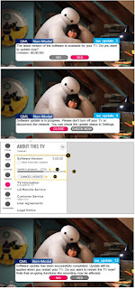
  Software update procedure USB (1) Insert the USB memory Stick to the USB port (2) Automatically detect the SW Version and show the bel...