Sunday, 15 December 2019

YAMAHA DIGITAL SOUND PROJECTOR YSP-4100 - YSP-4100 – Firmware update – Protection mode checking


Firmware update – Protection mode checking – Self diagnostics - Power supply schematic diagram - USING ICs MIP2F40MS – FAN5511- YAMAHA DIGITAL SOUND PROJECTOR YSP-4100 - YSP-5100

Updating firmware
When the following parts are replaced, the firmware must
be updated to the latest version by using the corresponding update method.
Updating the main microprocessor firmware - Main microprocessor (IC428, DSP P.C.B.), MAIN P.C.B.
Updating the DSP1 FLASH ROM firmware - DSP1 FLASH ROM (IC9, DSP P.C.B.), MAIN P.C.B.
Updating the Wireless Module Firmware and the AirWired microprocessor Firmware - AW-CARD P.C.B.
* The main microprocessor firmware and the DSP1
FLASH ROM firmware also can be updated by using the Firmware CD.
Confirmation of firmware version and checksum
Before and after updating the firmware, check the firmware version and checksum by using the selfdiagnostic function menu.
Start up the self-diagnostic function and select “18.ROM VER/SUM” menu.
Using the sub-menu, have the firmware version and checksum displayed, and note down them.
(See “SELF-DIAGNOSTIC FUNCTION”)
* When the firmware version is different from written one after updating, perform the updating procedure again from the beginning.
Initializing the back-up IC
Be sure to initialize the back-up IC after updating the firmware by the following procedure, otherwise the set up information (tuner preset, clock) can not be memorized properly.
Start up the self-diagnostic function and select “7. FACTORY PRESET” menu. (See “SELF-DIAGNOSTIC FUNCTION”) Select “7) PRESET RSRV” and turn off the power once and turn on the power again. Then the back-up IC is initialized.
Required tools
# Firmware downloader program......................... FlashSta.exe (For Main microprocessor firmware
Wireless module firmware
AirWired microprocessor firmware) ................. DSP_FLASHER_YSP2009.exe (For DSP1 Flash ROM firmware)
# Firmware
Main microprocessor firmware ...........................Y09_xxxx.mot Y09_xxx.id
DSP1 Flash ROM firmware ............YSP09HIa_data1_verx_xxr.hex
Wireless module firmware ................uaw_firmup_xxxx.motuaw_firmup_xxxx.id
AirWired microprocessor firmware .......................... uaw_card_xxxx.mot uaw_card_xxxx.id
# RS232C cross cable “D-sub 9 pin female
# RS232C conversion adaptor (Part No.: WR492800) (For Wireless module firmware / AirWired microprocessor firmware)
# Preparation and precautions
# Download the firmware downloader program and the latest firmware from the specified source to the same folder of the PC.
# Prepare the above specified RS232C cross cable.
# While writing the firmware, keep the other application software on the PC closed.
It is also recommended to keep the software on the task tray closed as well.
Updating the main microprocessor firmware 
Connection
# Disconnect the power cable of this unit from the AC outlet.
# Connect the RS-232C terminal located on the rear panel of this unit to the serial port (RS232C) of the PC RS232C .
Operation procedure
1. While pressing the reset switch (SW801 of the FL P.C.B.) using a fine tipped pin, connect the power cable to the AC outlet.
The power to this unit is supplied and the microprocessor is in the writing mode.
2. Start up FlashSta.exe.
The screen appears as shown below. (Fig. 2)
3. Select the data to be transmitted and port. (Fig. 2)
# Select Program
Select Internal flash memory.
# RS232C
Select the port of RS-232C
# For selection of the port, COM1 to 4 can be used.
As COM5 or higher port cannot be used, select out of COM 1 to 4 of the setting on the PC side.
4. Click [Refer...] and select the firmware name.
Main microprocessor firmware: Y09_xxxx.mot
* The ID and MCU Type are loaded automati cally when the file is selected.  Click [OK].
5. Click [Setting], and set the baud rate.
6. Click [E.P.R.], then the “Erase” screen appears.
7. Click [OK] to start writing.
8. When writing of the firmware is completed, the screen appears as shown below. Click [OK].
9. Click [Exit] to end FlashSta.exe.
Updating the DSP1 FLASH ROM firmware
Connection
# Connect the RS-232C terminal located on the rear panel of this unit to the serial port (RS232C) of the PC with RS232C cross cable.
Operation procedure
* Before start, the power cable of this unit from the AC outlet.
1. Start up DSP_FLASHER_YSP2009.exe. The screen appears as shown below.
2. Select the data to be transmitted and port. Click [COMx], then the “COMx opened!” screen appears.
* The port selection varies depending on OS of the PC.
Windows 98/2000/Me ...................... COM1 – 4
Windows XP .................................... COM1 – 2
As port other than the above cannot be used, select the port using the setting on the PC.
3. Click [...] and select the firmware name. DSP1 FLASH ROM firmware: YSP09HIa_data1_verx_xxr.hex
4. Click [RDY] to set to the standby mode.
5. Connect the power cable of this unit to the AC outlet.
6. Start up the self-diagnostic function and select “16-3. UPDATE TI” sub-menu.
7. Press the “ENTER” key on the remote control to start writing.
8. When writing of the firmware is completed, the screen appears.
When the writing is completed succesfully, displayed checksum in “SUM from FILE” is the same as displayed checksum in “SUM from SET”.
9. Click [Exit] to end DSP_FLASHER_YSP2009.exe
Writing method using the Firmware CD
# Required Tools
#DVD or CD player
(with DIGITAL OUTPUT (OPTICAL or COAXIAL) jack)
#  Optical cable (when OPTICAL jack is used)
#  Digital audio pin cable (when COAXIAL jack is used)
# Firmware CD
#To make the firmware CD, download the latest firmware from the specified download source.
Connection
Connect this unit and DVD/CD player with DIGITAL OUTPUT (OPTICAL or COAXIAL) jack
Operation Procedures
While pressing the “VOLUME +” key of this unit, connect the power cable of this unit to the AC out let
The FIRMWARE UPDATE mode is activated and “F/W Upgrader” is displayed.
2. Press the “STANDBY/ON” key of the DVD/CD player to turn on the power.
3. Press the “EJECT” key of the DVD/CD player to open the disc tray.
4. Load the firmware CD on the disc tray and press the “PLAY” key of the DVD/CD player.
The disc tray is closed and writing of the firmware is started.
5. When writing of the firmware is completed, “Update Success”, “Please...” and “Power off!!” are displayed repeatedly.
* When the version of the firmware to be written is the same as the one existing in this unit, “Same Version”, “Please...” and “Power off!!” are displayed repeatedly. (Updating is not necessary.)
If the display remains unchanged for more than 10 seconds after starting the firmware CD play procedure, perform the firmware CD play procedure again from the beginning. If “FILE CORRUPTED” is displayed after “Address:XXXXXX”, make sure that the written data is not corrupted and perform Steps 1 to 7 of “Operation Procedures” again. If “Upgrade Failed” is displayed, perform “operation procedures” from the beginning.
6. Press the “EJECT” key of the DVD/CD player to open the disc tray.
7. Unload the firmware CD from the disc tray and close the disc tray.
Starting Self-Diagnostic Function
While pressing the “VOLUME +” and “VOLUME -” keys of this unit as shown in the figure below, press the Power key on the remote control to turn on the power. The self-diagnostic function mode is activated.
Starting Self-diagnostic function in the protection cancel mode
If the protection function works and causes hindrance to trouble shoot, cancel the protection function as described below, and it will be possible to enter the self-diagnostic
function mode.
While pressing the “VOLUME +” and “VOLUME -” keys of this unit as shown in the figure above, press the “ ” (Power) key on the remote control to turn on the power and keep pressing those 2 keys for 3 seconds or longer. The self-diagnostic function mode is activated with the protection functions disabled.
In this mode, the “SLEEP” segment of the FL display of this unit flashes to indicate that the mode is selfdiagnostic function mode with the protection functions disabled.
CAUTION
Using this product with the protection function disabled may cause further damage to itself. Use special care when using this mode.
Power supply schematic diagram 
USING ICs MIP2F40MS – FAN5511

Wednesday, 11 December 2019

Service hints-TVs-My service experiences-Part 2

Grundig TV Model: ST70-460 (CUC4635 Chassis)
Intermittent start up and tripping
Dry joint on R636, vertically mounted 4.7 ohm wirewound in sw mode circuit

Nei TV Model: 2031TX
No Power
R802 open circuit. Unknown device (poss. Thermistor). Replaced with 15K, 2Watt

Sony TV Model: KV-2565MT (SCC-E64P Chassis)
Horizontal output transistor Q802 goes short repeatedly
C818 (1uF, 250v) had lost capacity, replaced C818 and Q802 and unit was ok

Sony TV Model: KVD-C21MF1 (SCC-K68A-A Chassis)
No sound and screen not appearing, B+ ok
No input on pin 5 of IC301 (MC44002P), R339 had failed, once replaced the unit was ok

Bush TV Model: 28ZKF
Set powers up but no sound and blank raster
RF10 o/c (33 ohm)

Panasonic TV Model: CT20G12V
Dead
this was found to be due to the STR58041 chip

Philips TV Model: GR2.4AA (GR2.4AA Chassis)
No picture, just black screen
Check R3414, an SMD chip on the CRT board. There could be invisible bad solder joints

Panasonic Video Model: NVJ40
Poor picture, may clear as unit warms up
Check C27 in the power supply secondary

Philips TV Model: TX2112 (U5N Chassis)
Sound mutes for too long when changing stations (up to 30 secs)
The MAB8441-T005 was faulty (no longer available)

Thorn Video Model: VR414LVA
Dead, no functions, no display
Replacing CP19 (1000uF, 10v) in the PSU restored operation
Goldstar Video Model: P13I
Dead, no functions, no display
Replacing CP19 (1000uF, 10v) in the PSU restored operation

Goldstar Video Model: P13I
E-E in playback & dim display
CP25 (100uF, 10v) in PSU cured dim display. No need to dismantle whole deck. W152 was ok

Thorn Video Model: VR414LVA
E-E in playback & dim display
CP25 (100uF, 10v) in PSU cured dim display. No need to dismantle whole deck. W152 was ok

Jvc Video Model: HR-S4700EK
Intermittently crunches tapes on eject
I had to use a clear service cassette to see what was occuring during the eject sequence and found that during the unthread, the take up reel was rotating anti-clockwise and was not being braked, the felt pad on the take-up sub brake had fallen off the arm, a new brake cured the problem

Firstline TV Model: 1433GR
Chopper secondary voltage (115V) was way too high (around 220V)
C615, Q605, Q606 and R308 had all died, The value of C607 (47uF) was out of range. Note: This set is equivalent to the Princess GT-1412

Sony TV Model: KV-HF14M80 (BG-3S SSC-U21F Chassis)
Dead in standby mode, no primary voltages, led orange
Change MICOM CXP86449-627S

Thomson TV (ICC17 Chassis)
Picture lacking in contrast and brightness
The symptoms suggested a beam limiter fault, replacing transistor TL02 (BF422) which was found to be leaky produced excellent pictures

Philips TV (L6.2 Chassis)
Power supply will not start up
Resistor 3506 (0.33 Ohms, 1w fusible) had failed, a replacement brought the set to life

Schneider TV Model: TV9
Line output transistor short circuit
Replacement did not clear the fault and the protection circuit was operating. C307 (0.047
uF, 200V) was found to be o/c, when removed it had a bubble on the side, its part of a potential divider network (C306 & C307 in series, centre of which goes to the protect circuit), it is hard to get to being right by the line output transistor

Beko TV Model: 14.2
The +Ub voltage (+140V) was not present, fault in switching power supply
Transistor T601 (SK2545) had failed, replace/check resistor R602 (1Meg ohm) in switch control circuit, also if T601 is s/c the control chip TDA16846 will also be damaged

Sony TV Model: KV25K5U (FE1/FE1A Chassis)
No sound or vision, front led flashing
Replaced line output transistor, re-soldered dry joints on driver transformer. Also check for any other poor joints in this section. Have used a 2SD1878 as replacement, This seems to work ok as the Sony original is very expensive

Sharp TV Model: 6GF63H (DA-50W Chassis)
Noise from speakers / center speaker even with the volume set at minimum
Replace IC1300 (BA4558F 8pin smd) and IC1302 (TDA7480) which are both located on the central speaker amplifier plug-in PCB

Jvc Video Model: HRJ205
Dead, no negative voltages on psu connector
Check R32 (100 ohms) in psu for o/c

Normande Spectra TV Model: 5207 (F11 Chassis)
Dead set, power supply ticking
R164 was found to be open circuit

Decca TV Model: D28NT92S (PT92 Chassis)
Dead set, no stby led
Check RP06 (3.9meg), RP05 (1meg) and RP07 (15R) in psu

Sanyo TV Model: Spectra 2000
Picture had only wide screen effect
Found set on the street! beautiful little 14" TV, still looks like new, replaced 33uF, 160v cap in power circuit as it was bleeding its guts onto the pcb, has worked perfectly ever since

Teac TV Model: CT-M685 (ONWA Chassis)
Set stays in standby intermittently or will int switch off to standby also brightness and contrast slightly low
Re-solder all joints in the power supply (very small dry joints that need a microscope to find !) also check / replace replace capacitors C109 and C110 and check condition of other psu caps.

Panasonic Video Model: NVJ30 (G-Deck)
Severe patterning of white streaks filling the screen in playback. E-E is ok
C1122 in the power supply unit. It is probably leaking its contents

Panasonic Video Model: NV-366
Front buttons (Play, FF etc.) don't work
Caused by faulty remote control jack socket - this machine uses a wired remote

Matsui TV Model: 1420T
Dead set, P.S.U. not firing up
Resistor R511 (1.8M) open circuit

Salora TV(J Chassis)
Start up problems
Replace CB712 and CB726 in the power supply. Both are same value (4.7uF, 50V)

Goldstar TV Model: 20A80
No picture, FR406 ok
Check the video output amplifier stage for failure

Panasonic Video Model: NV870 (D1 Mechanism)
Noisy FM audio
Add a 0.01uF 50v ceramic capacitor between pin 9 of IC4509 and ground (only applies to units with serial numbers prior to D5K)

Panasonic Video Model: NV870 (D1 Mechanism)
Mode switch chatters
If it still does this with a new mode switch, check the serial number. If it's prior to numbers beginning A5K... then add a 560 ohm resistor and a 50v 0.68uF electrolytic capacitor in series, between pin 2 of IC6002 and ground.

Panasonic Video Model: NVF70
No sound via SCART socket
Fit R4908 and R4910 on input/output pack, as they may be missing ! (Both 47 ohm)

Panasonic Video Model: NV730B (D1 Mechanism)
Video heads wear very quickly
Check the back tension if you haven't done so already - it was set too high when manufactured.

Sony TV Model: KV2020
Picture is folded over at the top and curled at the top left hand side
Replace C559 and C560

Sony TV Model: KV1412
Noisy picture
Replace relay RY481 on S2 board

Sony TV Model: KV1412
Vertical line at the left of the picture
Replace L506 on A board, replacement part number 1-407-366-00

Sony TV Model: KV1412
Set reverts to standby mode when switched on, because IC003 does not reset correctly
Replace IC003 on A board, IC type CX523013P

Medion TV Model: MD7103VTS (11AK18 Chassis)
Power LED and Sound OK. EHT Voltage for 1 Second after switching on via Remote Control
Replace vertical deflection circuit IC605 (TDA8361) - don
’t forget to apply Heat transfer compound.

Sony TV Model: KV28WS3 (AE3 Chassis)
No sound or picture, in protection after 2 seconds
No 6.5 Volt on G-board. Fuse resistor PS605 is broken on G-board. Cause: bad contacts

Philips TV (ANUBIS A-AC Chassis)
Low 95v rail, (35v)
C2530 open circuit completely

Panasonic TV Model: TX28W3 (EURO 1 Chassis)
At switch on a strange sound comes and goes for a few seconds, no sound and vision
Check R622, Q624 and T639

Grundig TV (CUC5310 Chassis)
Dead, no shorts found
Look for dry joints on the scan coil plug (may not be visible) also re-solder the 12v and 5v regs

Sony TV Model: KV21GMR1 MkII
No raster, fly back squeaking
Check the damper diode, in my case it was leaky, also check the electrolytic capacitor connected from the collector of the pin out trans.

Rca TV Model: F19220BK (CTC175L2 Chassis)
Erratic screen / intermittent, eprom causes multiple possible symptoms, clicks on/off, tuner, you name it !
Mass defect caused by bad solder in tuner, once fixed will probably last forever. Re-solder tuner wrap-around groundings and all pins under tuner shield (bottom), if no success suspect a corrupted eprom

Sony TV Model: KV20TS20
Snowy or intermittent picture, makes popping sound
Solder all coils in stand up board and tuner

Philips TV (A10E Chassis)
Randomly switching to scart input when the programme output from the tuner should be displayed
This is now becoming a common problem, the cause being the painter chip IC7064 which is located on the small signals panel, there are 8 different versions but only 3 common versions

Schneider TV Model: DTV2
shuts off after 20 minutes or so
Dry joint on FBT

Sony TV Model: KV-M21TU (AE1 Chassis)
Intermittent rolling and loss of luminance, improves as set warms up
Dry joints on tuner / IF board

Sony TV Model: KV-21FS100 (BA6 Chassis)
No power, R640 open
Change R640, IC600 and associated electrolytic capacitor

Philips TV-Vid Combo Model: Televideo
No vcr transport functions via remote
This is the symptom when the remote control has switched from the correct VCR1 mode to the VCR2 mode (usually due to low battery voltage or the batteries being replaced), to rectify the situation hold both the stop button and button 1 together for 5 seconds, alternatively for different remote versions holding the stop button and button 2 together for 5 seconds will rectify the problem

Toshiba TV Model: CF3060K
Problems with screen size
Look out for 2 x 2.2uF electrolytic (sometimes red in color)

Daewoo TV-Vid Combi Model: DVT-1482P (CP310 Chassis)
Totally dead except for a few rapid flashes from the green led at switch on
C811 a 100uF, 16v capacitor in the power supply was the cause, it is located next to the chopper transistor heat sink. This is the same TV/Video as the Goodmans TVC14VP

Panasonic Video Model: NV-HD675 (Z-Mech Chassis)
Intermittently shutting down with HO1 in display
Problem can be caused by stator board VEK9017 but in this case the problem was the upper drum assy! The bearings seize up when warm!

Sanyo TV Model: CEP3011V-30 (A1-B14 Chassis)
After switching on, no longer able to switch-off with remote control, standby light comes on with sound muted. (Original remote control: RM-700)
Opto-coupler PC113 faulty

Ge TV Model: PTK195AA (PTK195 Chassis)
Works fine for 10 or 15 min. (or sometimes 1 or 2 days) then bows from top and loses convergence
Replace the STK730-130, located on small board above the convergence module

Lenco TV Model: 14P1MNA
Standby only
Check R101 (4.7ohm), TR102 (C6180) and C126 (47uF, 16V)

Sony TV Model: KV-M1400 (BE2A Chassis)
Insufficient vertical deflection. Line rolling on top of picture
Replace ceramic capacitor C524

Tandberg / Seleco / Sinudyne TV Model: 3TS645 (PC170 Chassis)
No vertical scan, just one bright line in the middle
Suspect R235 (18kohm), in some cases the TDA3654 may also have failed

Grundig TV Model: M70-490/9 TEXT (CUC3800 Chassis)
No sound, picture ok
When shifting up the channel frequency using the fine tuning, a very weak sound could be heard. Replaced the sound IF demodulator chip U2829B(IC2110)

Sanyo TV Model: CEP2190M
No sound
IC901 (TDA4935) blown due to excessive supply voltage, capacitors C619, C623, C810, C600, C601, C859 defective. Also verify R822

Jvc TV Model: AV25S1EK
Field collapse
Re-solder TDA3654 as joints appear good but on application of soldering iron show to be dry

Mitsubishi TV Model: CS40503
sometimes will not power up, missing 15 volt standby
Replaced D982 and C982, both leaky

Sony TV Model: KV24FS100
Will not power, led blinking
check R640 (1K 1/4w) if open replace ic600 (8-759-670-30)

Schneider TV Model: STV630UK
Only half a screen of frame scan
Replace IC401 (TDA8177F). If any blanking problems occur after chip replacement, check R327 (1 ohm) next to IC401

Sharp TV Model: DV6632H (4BS-C Chassis)
Led changes from green to red, fails to start up, no EHT but secondary voltages in psu ok (150V ok)
Check Q601 and Q606, these are Q600 LOPT drivers, there should be 2V P-P on base of Q606 and 150V on collector of Q601, replace Q606 with a BC182 (check pinout)

Matsui TV Model: 25M3
Failure to start up, led pulses
Check for dry joints on R541 and D436 located next to L.O.P.T

Proline TV Model: 28N1 (F19 Chassis)
Procedure to invoke service mode
I have used this method and it works (supplied from the makers manual). With tv off, hold vol up button on tv, switch tv on and keep holding vol up button whilst pressing standby on remote (this must be done within 4 secs of switch on) at no time let vol go

Sharp TV Model: DV7045SN
No vertical deflection
R615 open (0.13 ohm 1/2W). Also re-soldered many bad solder joints

Jvc Video Model: HRD750
Tracking does not lock. Picture runs up and down occasionally
(Very) Small electrolytic caps on the drum circuit board must changed (They may be the bigger can type, if you don't find small ones)

Toshiba TV Model: 175T9B
Line tearing and incorrect field lock when cold
47uF electrolytic AGC decoupling capacitor inside tuner/if unit

Philips TV-Vid Combi Model: 14TVCR240
Poor tape transport, tape is crumpled, upper or lower side gets rippled
Replace the capstan roller, if the tape transport is still not smooth check the guidepole (between the audio/control head and the capstan), tape must touch border-ring. Adjust the audio head position (screws marked A and T)

Bluesky TV Model: TDX-70 (11AK19 Chassis)
HT low / missing
Q608 (BU2508) dead (short-circuited). Needed replacement. That's all...

Panasonic TV Model: TC2195DRS (Z3T Chassis)
SMPS noise. Low volt and high current on Usyst, no screen or sound
FBT TLF15606F

Irradio TV Model: MC-FBC-006
Dead, i.c. oscillating (may start if i.c. heated)
Check / replace R602 (2.2M, 1/2w)

Sony TV (FE-1 Chassis)
Procedure to return EEPROM to factory default settings
Select programme 59, enter the service mode and at the TT-- prompt enter 49 then 24 (for UK)and 08 then switch off at the mains
(Anonymous)
Sony TV (FE-1 Chassis)
Main p.s.u starts up then almost immediately shuts down
This was due to IC603 (SE135N) being faulty

Sony TV Model: KV-E2543E
Set goes to V protection mode (led flashes 13 times)
Check if there is saw signal at STV8379. If there is no signal, suspect dj in connector links between both motherboards, especially the one very close to plastic frame

Toshiba TV Model: 2505DB
Stretched frame or frame collapse
Replace modification diode 570 on copper side

Hitachi TV Model: C2846TN (311 Chassis)
Frame collapse or dotted line
Check and replace frame ic (TA8427K) or check R710 for open circuit, also check for possible dry joints on D601

Sony TV Model: KV-A2923
Set starts, horizontal and vertical deflection work, HT ok, crt heaters ok, but no sound or picture
I turned the G2 voltage up and noticed a white screen with flyback lines, frame ok. I detected two badly soldered double diode rectifiers in the secondary part of the power supply. I checked all other joints, and everything was ok, success

Hitachi TV Model: C1714T
Frame collapse, causing set to go dead, also can cause the regulator transistor, to go s/c. BUT12AF. H.T. unstable
Check R951 (39K) goes high, in this case 65K, causing HT to go high

Philips TV (GR2.1 AA Chassis)
Poor picture quality from CVBS EXT1 and EXT3. Low intensity high saturation. Loss of sync. Shock and temp dependent
Dry joints on SMD resistors 3014 and 3019 on IF/Sound module other side of encapsulated TDA2549

Sony TV Model: KV-A2923
Standby led blinks slowly, a few times, chassis won't start up
I changed the vertical deflection ic type TDA8170 and I measured two leaky capacitors in the power supply. Better to change all 4 capacitors in the power unit, everything was then ok.

Sony TV Model: KV21M1D
Picture disappears a moment after changing program. Raster/OSD ok
Replace TDA9806 ic

Goldstar TV Model: CBT-9745 (PC91A Chassis)
Attempts to start up. When main switch is pushed ON, relay coupling and decoupling (on-off, on-off)
Replace: C805 (47uF, 50V) next to the TDA4605 and C801 (1uF, 50V)

Goldstar TV Model: CBT-9745 (PC91A Chassis)
TV dead. PSU ok, led lit. When button pushed on remote the LED goes out but set does not start (Missing HF voltage)
Replace: C417 (1uF, 250V) Elko for HF oscill. (next to HF trafo)

Philips TV (FL1.1AA Chassis)
Int shutdown with lights flashing
Check the 18v zener D6376

Philips TV Model: 20PV164-05
Vertical frame collapse
Change vertical output drive IC and nearby electrolytic capacitor

Nokia TV (FX Chassis)
Left part of picture missing after fitting vertical modification kit
Make sure you have fitted the extra capacitor between pins 8 and 9, instead of 10 and 9. Fitting incorrectly will destroy the sandcastle pulse and make the picture appear strange

Nei TV (CE25 Chassis)
Dead - PSU clicking
Dry joints on D116 and C131 causing blown BU508A

Grundig TV (CUC5310 Chassis)
Picture int disappears leaving snow on screen
Resolder the Xtal in the tuner

Schneider TV Model: STV630UK
Frame Collapse
Replace IC401 (TDA8177F) and resistors R325, R326, R327

Matsui TV-Vid Combi Model: TVR185
Int sound
Check voltage on sound IC, if it drops with high volume change C620 (1000uF, 25 vdc)

Sharp TV Model: 66GF-63H
Blank grey raster with fly back lines, sound present and ok
Check pin 2 on connector H on tube base for 12V if high then check Q912 (BC337) for o/c

Sony TV Model: KF60XBR800
No picture no sound timer light flash 44 fast 45 then 5 times then 5 times
Replace power block part # 1-468-510-11

Toshiba TV Model: 198X6M
Horizontal output continues to short
Check capacitors C403 and C408 (both 50v) these two caps tend to change capacitance

Philips TV Model: 28PW6005 (A10 Chassis)
Changes to ext 1 when watching tv (ok with video input)
Painter ic IC7064 failed on the ssb (small signals board)

Philips Video Model: Turbo Deck
Chews tapes and poor tracking
Fit new pinch roller

Thomson TV Model: RP46
East-west and north-south bowing. Really bad convergence
The extra power supply is not working. Check R18 on primary side. It should read 220k Ohm

B and O TV Model: LX5500
Sound disappears from time to time
If there is sound all the time via scart, but problem with both mono and stereo via tuner, check R137. It is a 4k7 pot on the tuner board

Rca TV Model: F27442 (CTC203AD5 Chassis)
No power, all standby voltages ok
Replace the guide plus. is located to the side of the tuner


Bush TV Model: 2071NTX (11AK19 Chassis)
Black screen from tuner but OSD (menus and channel no.), teletext and sound work normally
Q500 and Q504 blown, replacement cured fault. Removing R508 also restored picture. Fault puts TDA8840 in RGB insertion mode continuously, so separated RGB input might still work

Magnavox TV Model: RP2781 C101 (27X105-00AA Chassis)
No vertical deflection
If resistor R445 (1 ohm) has gone open circuit this may cause IC550 (LA783x) to also fail. Replaced both IC550 and R445

Sony TV (FE-1 Chassis)
Procedure to display past error codes and the number of times they have occured (particularly useful for ongoing intermittent faults)
Enter the standby mode then press the on-screen display button (i+), 5, volume down, and finally the tv button. Note: the error count can be reset by pressing 8 then 0 on the remote control

Sony TV (FE-1 Chassis)
Intermittently displays bright red/green/blue raster then shuts down with led flashing 2, 4 or 5 times
Amazingly this was due to the CRT being faulty !

Philips TV Model: 33SL5796/16B (FL 1.0 Chassis)
Snowy picture specially in VHF band. After about 5 minutes, picture snowy in all bands. About 10 minutes after switching on, no picture nor sound, just snow on the screen.
replaced the TUNER/IF. Original code was FQ816ME which is no longer in production. Replacement code is FQ916DME

Sony TV Model: KV-21RXR1
Excessive brightness/ brightness control reverses its function
When setting brightness to minimum the pic became very bright, setting to maximum the picture became dark ! Found that R301 (270k ohms) near the jungle IC was o/c

Philips Video Model: VR6448 (20921 Chassis)
Mechanism jammed, some posts hard to turn
Grease has turned into cement!! Oil most of the moving parts, and move them to ensure oil penetrates

Universum TV (11AK19 Chassis)
Narrow Picture
After re-soldering joints in the line output stage, check R629 (27 ohms, 1/2w) safety resistor to E/W FET, also o/c capacitor C630 (0.47, 250 volts). According to the schematic R629 is 2.7 ohms

Philips TV Model: 14PV220 (EPSILON 2001 Chassis)
Dead (Totally)
SMPS Chopper IC 7310 (MC44608 P75). I had no output from pin 5 with start up voltage pin 8 OK at 290V. If start up missing check start up resistor 3335 (1K). The only source I found for IC 7310 was Philips direct, part number 9322-143-51682


Philips TV Model: 21GR2751 (G90B Chassis)
Stereo set with no sound off air, maximum volume produces low hiss, some sound possible if station is detuned slightly. Sound via SCART is ok
Replace IC U2829B on audio panel

Nordmende TV Model: GALAXY 55 (ICC8 Chassis)
Dull picture
Replace (TT33) on tube base

Nordmende TV Model: GALAXY 55 (ICC8 Chassis)
Not tuning into channel
33v missing (RH040) o/c

Telefunken TV Model: PALCOLOR F531 (ICC9 Chassis)
Stand-by led flash but set does not start
Replace: TL19 (BUH517), DL21 and DL22, CL21 and CL22

Orion TV Model: TV2501B
Dead set or will start up and shut down
IRD shorted or leaky

Sony TV Model: KV2062
Dark picture, No brightness control
1000V+ Missing caused by open circuit IK resistor Near to FBT

Sony TV Model: KVFX29 (FX Chassis)
White horizontal line (no vertical deflection)
Check / replace R548, R549

Goldstar TV Model: CB20A86
Dead, F801 blown
Check short circuit PTC coil (Degauss) short Diode on main Cap+ Check for failure of regulator IC801 (STR5707), Also check H.output D1651 for short circuit

Toshiba TV Model: 32ZD09G (C00S Chassis)
Procedure to enter the service mode
Press the mute key on the handset once, then press the mute key for a second time but hold it down while also pressing the menu button on the set

Schaub Lorenz TV Model: DS2 (DTV2 Chassis)
Procedure to enter service mode
Press and hold service button on PCB inside TV. Press `C` on remote. Press program no. where your test picture is, You are now in service mode

Akai Video Model: VSG2DPL
Tape loading carriage is very loose and sloppy will not load and eject tape properly
Mode switch is faulty, out of alignment or has a bad connection back to the PCB. This switch is located underneath the tape drive mechanism

Samsung TV Model: CB7230WT
Power supply flutters and standby light dims out
Replace mains filter capacitor (220uF 400v), also make sure the 4 capacitors in the primary are replaced (if they haven't already been)

Samsung TV Model: CB7230WT
Vertical failure (common fault)
The reason for the failure is because the yoke is low impedance. The TDA3654Q i.c. has been designed to handle 12 ohms and over. Heat is the reason it destroys itself, the best cure is to place a small cpu fan on the heatsink

Philips TV Model: 29FL1770 or 25FL1760 (FL1.0 Chassis)
After replacing the line output transformer, the following symptom was displayed. Display flashing standby light and stereo II
Short s23 and s24 briefly, which will put the set into service mode. Option 1 should read 010 this applies only to the 25FL and 29FL. Option 2 should be 001 for sets with text and 004 for sets without text

Jvc TV Model: AV28WZ2
Blank raster
Replace defective TDA6111Q for Red, Blue and green

Thomson TV Model: 28VK-44E
No start-up when cold, warm OK
Changes CP198 (47uF, 16v). Secondary Power supply

Philips TV Model: 14PV184
Dead set / blown fuse
Replace D6313, 6314, 6315, 6316 and R3337 (2R, 5W)

Panasonic TV Model: TX21AD2DP
Stuck in standby but tripping, not the usual nvm problem and nothing s/c
Check and replace C804 (1uF, 25V), C806, C807 (100uF/50V) in supply. Use 105 degrees cap. types
(Rob's TV-service - Holland)
Philips TV Model: 25FL1760 (FL1 Chassis)
Set tries to go to stereo as indicated by the on screen display, but most of the time it is stuck in mono, when in stereo the right channel was hissing
Replace the TDA8415 on the stereo decoder board, confirm this buy putting multimeter on pin 7 and 8, they should have a voltage of 3.2 volts

Philips TV Model: 29FL1770 or 25FL1760 (FL1 Chassis)
No pictures or sound
Disconnect the P1 and P2 plugs on the right hand side board. L.o.p.t. side. If the set now starts up then change all sound output IC's

Philips TV Model: 29FL1770 or 25FL1760 (FL1 Chassis)
When selecting a channel it locks in initially but will then go off tune (as if the voltage tuning had varied)
Replaced the TDA i.c. in the tuner i.f. section. (tried the capacitors first of course).

Philips TV Model: 29FL1770 or 25FL1760 (FL1.0 Chassis)
Lights flashing at the front, if carefully interpreted they point to the primary of the power supply
Replaced 2SB 3795B chopper transistor, heated the heatsink with a hair dryer and it started right up, weird as the transistor was reading fine

Decca TV Model: D20RDE6 (D Series Chassis)
No luminance(looks negative picture)
We spent over 2 hours on this set and in the end we swapped the chassis with a scrap chassis and the fault remained ! It turned out the fault was with the CRT

Samsung TV Model: 20A5
Partial field collapse
Check IC301 (TDA8350Q) and the 2 associated unmarked capacitors (10uF and 100uF, 63v) and the 10 ohms,5w ceramic resistor across pins 3/5 of the above chip

Sylvania TV Model: SRT2127ST
TV will not start up, fuses ok
Change IC601

Panasonic Video Model: NVJ45 (G DECK Chassis)
Appeared to be dead (like C1110 1uF, 400)
Found C1125 and C1130 (680uF, 20v) leaking onto pcb. Remove sm.tx and clean board

Orion TV Model: TV2501B
Dead set
Found the IRD shorted

Telefunken TV Model: Palcolor S540C (ICC9 Chassis)
Geen blauwe kleur
SMD transistor TV81 (Bc858) defect.

Samsung TV/Video Combi Model: VM3105
No video, no audio. High pitch sound from power supply.
Replaced blown fusible resistor R417 (1 ohm, 1/2 watt)

Bush TV Model: WS6690D (11AK19 Chassis)
At switch on front l.e.d turns green, blinks twice then set returns to standby. All h.t voltages rise, then fall away as set goes into standby
33 ohm resistor feeding standby 5V reg was high (8 ohms - not shown cct diagram), in my case D605 on the 45 volt supply from the LOPT was faulty, although it measured o.k

Thomson TV (TX807 Chassis)
Plain raster, retrace lines, no sound
Problem in vif board, Resistor 68 ohms to +b supply line 12V
Hitachi TV Model: C2146TN
Dead / int, led lit
Check the 5v regulator IC952, 8v regulator IC951, standby regulator IC950 and the field output chip (TA8427K) or for dry joints on the regulators

Nordmende TV Model: F20-9 (ICC7 Chassis)
No colour
Check IV01 (TA8659) or IE50 (TEA2114)

Goodmans TV Model: 2029T
Blank raster with no sound (eht & tube heaters present)
ZD401 s/c. Also take a look at R419. This set had been left on and R419 had cooked, it's value went to 20K

Sony TV Model: KVG25M1
Dead
Found Q802 (C4927) short, replace with same type as no other types last

Panasonic TV Model: TX-2470
Cogging on vertical elements of picture, p.s.u squealing
Replaced C808 (10uF, 50V) It had gone low in value

Panasonic TV Model: TX21V1 (Alpha 2 Chassis)
Bright red raster with flyback lines,shutting down after about 30 seconds with squealing from power supply
The fault was due to the supply choke to the red output stage on the tube base panel being O/C, I can only assume the shut down was due to excessive beam current, a long soak test proved all was now ok.

Philips TV Model: 20PT3742
Dead with LED blinking 4 times
The vertical output IC. is short circuit

Panasonic Video Model: NVG30
Operates for about half hour to an hour and shuts down
Capstan IC located on the underside of main PCB was dry jointed due to exessive heat. Remove and discard plastic cover and apply fresh solder removing old. Also refresh heat sink compound.(I'll try extending the heat sink too)

Ferguson TV Model: M8422U (ICC17 Chassis)
LED flashes once the 6 times then goes to standby
Replace LOT

Philips TV (L6.3 Chassis)
Failure of fusible resistors R3929 and R3930 (both 560R)
Unfortunately when these blow it is a sure symptom of LOT failure. When replacing these resistors, check the big blue 470nF, 250V capacitor behind them for signs of heat damage and replace if necessary, to avoid a recall (With resistors gone again)

Aiwa TV Model: VXT1400
When switching to STBY raster remains and buzz noise is heard from the speakers
Cause: +B voltage (103 V) does not switch-off. Remedy: Replace defective C541


will continue

Tuesday, 10 December 2019

Service hints – TVs – part-1 - My service experience

TV service help: My experience in service field
Hitachi TV Model: C2133TN (Nokia Stereo Plus) Chassis)
Very strong red content in the picture, sometimes the fault would clear with the strong red content fading until the correct greyscale was achieved
After much searching around i found the problem. There was a very small crack in the solder at RH23, this is a 2K4 surface mounted resistor located at the back of the tube base. Resoldering both sides of it cured the fault.


Jvc TV Model: C-V14EKS/B/W (Onwa Chassis)
No Red
I was hoping the nvm had become corrupt and turned the red drive down but it was fine (To enter service mode press and hold vol up and vol down on the front panel and switch set on). Thankfully ZD405 (8V2) had expired (almost s/c) and removed the red.


Sanyo Video Model: VHR776E
Dead
Check and replace PR512 (which is located towards the front right hand side)


Nikkai TV Model: BABY 10
No / int luminance
Poor contacts within the service switch.


Sony TV (AE1 Chassis)
Field non linearity and short picture
Check / replace C531 (680uF, 25v), only slightly leaky, but a new one cured the fault.
Philips Video Model: VR200
Unit not working, no FL display, ticking from PSU, head drum twitching
Electrolytic cap in PSU primary dried up (47uF, 50v)


Ideal/Slx TV Model: IDTV28T/IDTV28N/SLX28T2/28N (SM2 Chassis)
EW fault then set went dead (tripping), R711 on EW panel burnt
Check for dry joints on C620 (0.47uF, 250V), if dry replace then check Q602 and R618 (5K6). Also it is worth replacing Q580 anytime these sets come into the workshop with a BF422


Philips TV Model: 25PT4423 (L6.2 Chassis)
Stuck in standby, LED on, no HT
There may be no 5V to the microprocessor. Check R3509 and D6501. Replace R3509 with a 47k 1 Watt version (4822 053 10473). D6501 is type BZX79B5V6 (4822 130 34173). Check the +150 volt rail, 145V is too low.


Rca TV Model: F27442 (CTC203AD5 Chassis)
No picture and sound, only a high pitch sound at switch on
Remove horizontal transistor and measure the resistance across any two pins. This value should be no less than 200ohms.


Sony TV Model: KV-M2131U (BE1 Chassis)
Intermittent loss of syncronisation, both horizontal and vertical
The surface mounted power transistor on the teletext module requires resoldering. As there is evidence of scorching on the board the use of a more substantial component would be indicated perhaps with small heatsink.


Samsung TV Model: CZ-21D83NS
Double picture or raster shifted
Check R414 (15K)
Sony TV Model: KV2565
Dead with H. output short circuit, replacment blows short again
First check power area and repair dry joints then change all high voltage (PF value) capacitors in the horizontal section, this fixed the problem.


Mitsubishi TV Model: CT29B2STX
Various faults, dead, int. dead, poor frame, poor E-W
Change all electrolytic capacitors in the primary. Check all large electrolytics in the secondary (Ie bigger that 470uF), check all capacitors around IC950 (error amp.). Most capacitors you will find are leaking electrolyte.


Sony Video Model: SLV-E800
No picture - screen is empty. Sound is ok
Check IC101 (BA7630F), if video signal comes to input (pin 1) but not present at output (pin 14) then replace this IC.


Panasonic Video Model: NVHD650B
Fault code F80. works occassionally then doesnt work at all
There is a plastic piece on the motor which rotates when you press play or eject. A plastic cap fits on the spindle of the motor. This slips and doesnt grip the motor hence does not turn the drive gears. Just glue or replace the part (use loctite or super glue)


Philips TV (A10 Chassis)
Procedure to view customer service menu
Press Mute button on handset and any button on the TV, hold for a few seconds and menu will appear.


Ferguson Video Model: FV105HV
Vcr dead, slow oscillation in p.s.u
Replace CP007 and CP008 close to the U4614B (Found this tip posted under Thomson VPH6601 which seems to have the same PSU)


Philips TV Model: 32PW6526-05 (SA10E Chassis)
Procedure to exit child lock with pin unknown / "locked" displayed on screen
Switch set on, press menu, select feature and press enter, select parental lock and press enter, then enter the code 0, 7, 1, 1 twice, the lock should now have cleared.


Fermendi TV (F19 Chassis)
Procedure to invoke service mode
I have used this method and it works (supplied from the makers manual). With tv off, hold volume up button on tv, switch tv on and keep holding volume up button whilst pressing standby on remote (this must be done within 4 secs of switch on) at no time let volume go, press the yellow memory button on the handset to storeToshiba TV Model: 28W23B (11AK37 Chassis)
Procedure to enter the service mode
Press the menu button then 4,7,2,5


Toshiba TV Model: 28W23B (11AK37 Chassis)
Picture displaced vertically, picture too high or low
This problem was cured by entering the service mode (menu then 4,7,2,5), then pressing the green fastext button to access geometry settings, selecting VP1 (vertical position) and adjusting as necessary.


Sony TV (BE3D Chassis)
Procedure to enter the service mode
Press standby, i, 5, vol+ and tv (TT should now be displayed on the screen indicating the set is in the service mode)

Grundig TV (CUC7301/3 Chassis)
Power supply blown
This is often caused by a dry joint at C669 in the snubber network but also check the mains bridge rectifiers reservoir capacitor (47uF, 385v) for o/c, this item is not included in the ususal p.s.u repair kits and if not checked may result in a repeat blow up.

Sony TV Model: KV32TS20
Dead no click, Q502, Q601, Q602 shorted and blown fuse 602
Change all the above parts and also check R647, C512, C525, D607, D608, D609, D610, D622, VDR601 off primary side of T605. I`ve also found T605 bad too. ToughDog, Sony has bulletin out on this model.

Sony TV Model: KV32TS20
Dead, good tip that I always use to save changed parts after replacing Q502, Q601, Q602 and blown fuse 602
I hook up 100 watt light bulb across fuse conection, then turn on tv, if light is very bright you still have a short. You saved the parts you changed, light should be dim and or blinks

Sony TV Model: KV27TS20
Intermittent video or snow
Resolder points A, B, C, D in tuner PCB, check cold solder on tuner shield 2-106-349-21

Ferguson Video Model: FV70B
Dim display
Check capacitor CP41 (220uF, 10v)

Panasonic Video Model: NV-L20
Poor playback and recording (looks like poor heads). Also shows as interference when playback appears
Check all electrolytic capacitor/s  in secondary of switch mode power supply

Hitachi Video Model: VTM640
Low video level
Replace C1530 (47uF, 16v)

Jvc Video Model: HRJ235EK
Rubbing noise at start of full tape with horizontal picture judder
Excessive take up tension! Replace take up clutch item 25, Pt no PQ46323A-1

Vestel TV (11AK19 Chassis)
Dead, ticks from switch on
Lop transistor dead short (BU2508AF) also check cap (12nf)

Bush TV Model: WS6671 (11AK19 Chassis)
Very low width and bowed verticals,no ew correction. R626 o/c
C630 (390nF, 300v) faulty, located next to scan socket. This fault can also be caused by R629 (2R7 fusable) o/c. In my set C630 was dry-jointed but not faulty. Check generally for dry joints in the E/W and PSU areas. Note that R629 is a safety component

Ferguson TV Model: TX98 (TX98 Chassis)
Intermittent tripping and switching to channel 1
Replace IC11 (TDA8138) 5/12 volt regulator ic

Metz TV (11AK20 Chassis)
Switches to standby when hot Check 4.00Mhz Xtal

Sony TV Model: KV-M1400D (BE2A Chassis)
Retrace lines on picture, 60V on RGB transistors
C700 (100nF, 250V) seems to be leaky, but main problem is R723 which had gone from 27R to 1.2M, both on CRT board.

Sony TV Model: KV-M1400D (BE-2A Chassis)
Dead, after replacing ic601 (STR54041) and Q601 (BC637) standby led blinks red twice, then blank, no HV
Replace fuse p801 (ICPN15 - 0.6A 50V, TO92)

Amstrad Video Model: DD8900
Bottom deck fails to load tape when pressing play/record. Sounds like loading motor is labouring when the pinch roller engages capstan shaft
The loading may complete if black pulley wheel on motor drive is 'helped'. Look for stiff linkages before suspecting Motor.

Tatung TV (F Series Chassis)
Starts up with black raster, then shuts down with LED blinking 4 times
This is the micro telling you that the auto grey-scaling procedure has failed. Change resistors R909, R913 & R922 (180k, 1%) on crt base PCB. You will probably find that all these have gone high.

Matsui TV Model: 1408T
Locked out by incorrect pin number being used - and Dixon's want 25 to do this
1: Press standby on remote control to switch TV on
2: Press volume minus button on set front, while pressing 7 on remote control for at least two seconds, until 'OK' appears in the middle of the screen.

Panasonic TV Model: TX28W3 (EURO 1 Chassis)
No raster, only heard a pip from speakers that went after a few seconds
C623 and R628 changed.


Will continue:-


Saturday, 9 November 2019

Acer Aspire laptop – Troubleshooting.


Acer Aspire laptop troubleshooting – Intermittent problem – Video problem – Audio problems – HDD related problems
Computer Shuts Down Intermittently
If the system powers off at intervals, perform the following.
1. Makes sure the power cable is properly connected to the computer and the electrical outlet.
2. Remove all extension cables between the computer and the outlet.
3. Remove all surge protectors between the computer and the electrical outlet. Plug the computer directly into a known serviceable electrical outlet.
4. Disconnect the power and open the casing to check the Thermal Unit and fan airways are free of obstructions.
5. Remove all external and non-essential hardware connected to the computer that are not necessary to boot the computer to the failure point.
6. Remove any recently installed software.
No POST or Video
If the POST or video does not appear, perform the following, one at a time.
1. Make sure that internal display is selected. Switching between internal and external by pressing Fn+F5. Reference Product pages for specific model procedures.
2. Make sure the computer has power by checking for one of the following:
# Fans start up 3 Status LEDs illuminate
3. Drain stored power by removing the power cable and battery. Hold the power button for 10 seconds.
4. Connect the power and reboot the computer.
5. Connect an external monitor to the computer and switch between the internal display and the external display is by pressing Fn+F5.
6. If the POST or video appears on the external display only.
7. Disconnect power and all external devices including port replicators or docking stations. Remove any memory cards and CD/DVD discs.
8. Start the computer. If the computer boots correctly, add the devices one by one until the failure point is discovered.
9. Reseat the memory modules.
10. Remove the drives.
Abnormal Video
If the video appears abnormal, perform the following, one at a time.
1. Boot the computer.
# If permanent vertical/horizontal lines or dark spots appear in the same location, the LCD is faulty and should be replaced.
# If extensive pixel damage is present (different colored spots in the same locations on
the screen), the LCD is faulty and should be replaced
NOTE:Make sure that the computer is not running on battery alone as this may reduce display brightness.
2. Adjust the brightness to its highest level. Refer to the User Manual for instructions on adjusting the settings. If the display is too dim at the highest brightness setting, the LCD is faulty and should be replaced.
3. Check the display resolution is correctly configured:
# Minimize or close all Windows.
# If display size is only abnormal in an application, check the view settings and control/mouse wheel zoom feature in the application.
# If desktop display resolution is not normal, right-click on the desktop and select
Personalize Display Settings.
# Click and drag the Resolution slider to the desired resolution.
# Click Apply and check the display. Readjust if necessary.
4. Roll back the video driver to the previous version if updated.
5. Remove and reinstall the video driver.
6. Check the Device Manager to determine that:
# The device is properly installed. There are no red Xs or yellow exclamation marks
# There are no device conflicts
# No hardware is listed under Other Devices.
Sound Problems
Perform the following, one at a time.
1. Boot the computer.
2. Navigate to Start > Control Panel > System and Maintenance > System > Device Manager. Check the Device Manager to determine that:
#The device is properly installed
# There are no red Xs or yellow exclamation marks
# There are no device conflicts
# No hardware is listed under Other Devices
3. If updated recently, roll back the audio driver to the previous version.
4. Remove and reinstall the audio driver.
5. Make sure that all volume controls are set mid range:
# Click the volume icon on the taskbar
# Drag the slider to 50. Confirm that the volume is not muted.
# Click Mixer to verify that other audio applications are set to 50 and not muted.
6. Navigate to Start´ Control Panel´ Hardware and Sound´ Sound. Confirm that Speakers are selected as the default audio device (green check mark).
NOTE:If Speakers does not show, right-click on the Playback tab and select Show
Disabled Devices (clear by default).
7. Select Speakers and click Configure to start Speaker Setup. Follow the on-screen prompts to configure the speakers.
8. Remove any recently installed hardware or software.
9. Restore system and file settings from a known good date using System Restore.
10. If the issue is remains, repeat step 9, selecting an earlier time and date.
11. Reinstall the Operating System.
Microphone Failure
1. Check that the microphone is enabled. Navigate to Start > Control Panel > Hardware and Sound > Sound and select the Recording tab.
2. Right click on the Recording tab and select Show Disabled Devices (clear by default). The microphone appears on the Recording tab.
3. Right click on the microphone and select Enable.
4. Select the microphone then click Properties. Select the Levels tab.
5. Increase the volume to the maximum setting and click OK.
6. Test the microphone hardware:
# Select the microphone and click Configure.
# Select Set up microphone.
# Select the microphone type from the list and click Next.
# Follow the on-screen prompts to complete the test.
Other Functions Failure
HDD Not Operating Correctly
If the HDD fails to operate correctly, perform the following:
1. Disconnect all external devices.
2. Run a complete virus scan using up-to-date software to confirm the computer is virus free.
3. Run the Windows Vista Startup Repair Utility:
a. Insert the Windows Vista Operating System DVD in the ODD and restart the computer.
b. When prompted, press any key to start to the operating system DVD.
c. When the Install Windows screen appears, click Next.
d. Select Repair your computer.
e. When the System Recovery Options screen appears, click Next.
f. Select the appropriate operating system, and click Next.
NOTE: Click Load Drivers if controller drives are required.
g. Select Startup Repair.
NOTE: Startup Repair attempts to locate and resolve issues with the computer.
h. When complete, click Finish.
If an issue is discovered, follow the on-screen information to resolve the problem.
1. Run the Windows Memory Diagnostic Tool. For more information see Windows Help and Support.
2. Restart the computer and press F2 to enter the BIOS Utility. Check the BIOS settings are correct and that CD/DVD drive is set as the first boot device on the Boot menu.
3. Confirm all cables and jumpers on the HDD and ODD are set correctly.
4. Remove any recently added hardware and associated software.
5. Run the Windows Disk Defragmenter. For more information see Windows Help and Support.
6. Run Windows Check Disk by entering chkdsk /r from a command prompt. For more information see Windows Help and Support.
7. Restore system and file settings from a known good date using System Restore.
8. If the issue is not fixed, repeat the preceding steps and select an earlier time and date.
9. Replace the HDD.
Intermittent Problems
Intermittent system hang problems can be caused by a variety of reasons that have nothing to do with a hardware defect, such as: cosmic radiation, electrostatic discharge, or software errors. FRU replacement should be considered only when a recurring problem exists.
When analyzing an intermittent problem, perform the following:
1. Run the advanced diagnostic test for the system board in loop mode at least 10 times.
2. If no error is detected, do not replace any FRU.
3. If an error is detected, replace the FRU. Rerun the test to verify that there are no more errors.
Undetermined Problems
The diagnostic problems does not identify which adapter or device failed, which installed devices are incorrect, whether a short circuit is suspected, or whether the system is inoperative.
Perform the following procedures to isolate the failing FRU (do not isolate non-defective FRU).
NOTE: Verify that all attached devices are supported by the computer.
NOTE: Verify that the power supply being used at the time of the failure is operating correctly.

1. Remove power from the computer.
2. Visually check them for damage. If any problems are found, replace the FRU.
3. Remove or disconnect all of the following devices:
# Non-Acer devices
# Printer, mouse, and other external devices
# Battery pack
# Hard disk drive
# DIMM
# CD-ROM/Diskette drive Module
# PC Cards
4. Apply power to the computer.
5. Determine if the problem has changed.
6. If the problem does not recur, connect the removed devices one at a time until failing FRU is found.
7. If the problem remains, replace the following FRUs one at a time. Do not replace a non-defective FRU:
# System board
# LCD assembly.

Wednesday, 6 November 2019

How to assemble the Jig cable to switch on the source cards. LG LCD – LED TVs


JIG Switching Source Cards LG. Jig assembly for Source test (ON and OFF symptom).
How to assemble the Jig cable to switch on the source boards. Using a source cable.   Follow the steps below.
1. Using a power cord
2. Separate only the pins necessary to switch the power supply.
3. Always check the source plate for the switching pins.
4. Necessary pins for the switching (PWR_ON + 3,5V + DVR_ON).
5. After this separation cut the wires to 6 cm length and put short the wires and insulate with electrical tape.
6. Put the Jig cable in the source and check if the source will turn on.
7. Table of pins required for family switching.

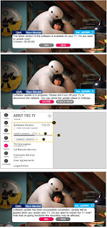
LG 32LK610BPUA, LG 32LK610BBUA LCD TVs – How to upgrade the software, fault checking method

  Software update procedure USB (1) Insert the USB memory Stick to the USB port (2) Automatically detect the SW Version and show the bel...