Wednesday, 19 June 2019

Harman Kardon SUB-TS7 SUB-TS8 sub woofer schematic and alignment


Sub woofer schematic and alignment; Test Set Up and Procedure
Equipment needed:
# Function/signal generator/sweep generator
# Integrated Amplifier
# Multimeter
# Speaker cables
Initial Control Settings:
# Power Switch OFF; Filter OFF
# Level MIN (Full CCW)
# Phase, Auto/On switches do not matter
General Unit Function (UUT = Unit Under Test)
1) From the signal generator, connect one line level (RCA) cable to the Subwoofer Line Level Input jacks L/R on the UUT. Use a Y-cable from a mono source if necessary to connect to both inputs. Do not connect to the single, purple SUB input.
2) Turn on generator; adjust to 75mV, 50 Hz.
3) Plug in UUT; turn the power switch ON. Turn LEVEL control full clockwise (MAX)
4) LED should turn from Amber to Blue (on top of UUT); immediate and vigorous bass response should be heard and felt from port tube opening.
5) Turn off generator, turn LEVEL control full counterclockwise (MIN), and disconnect RCA cable.
6) Connect one pair of speaker cables to Speaker Level input terminal (IN) on UUT. Cables should be connected to an integrated amplifier fed by the signal generator.
7) Turn on generator and adjust so that speaker level input at the amplifier is 1.6V, 50 Hz. Turn LEVEL control full clockwise.
8) LED should turn from Amber to Blue; immediate and vigorous bass response should be heard and felt from the port tube opening.
Sweep Function
1) Follow steps 6-8 above, using a sweep generator as a signal source.
2) Sweep generator from 20Hz to 300Hz. Listen to the cabinet and drivers for any rattles, clicks, buzzes or
any other noises. If any unusual noises are heard, remove woofers and test.
Driver Function
1) Remove woofer from cabinet; detach + and - wire clips.
2) Check DC resistance of woofer; it should be 3.0 ohms +/-10%
3) Connect a pair of speaker cables to driver terminals. Cables should be connected to an integrated amplifier fed by a signal generator. Turn on generator and adjust so that speaker level output is 5.0V.
4) Sweep generator from 20Hz to 1kHz. Listen to driver for any rubbing, buzzing, or other unusual noises.
Schematic
Improved filter performance                                                                             
Change four 1/6W +/-5% CF Resistors in the PREAMP PCB of the HKTS 7 subwoofer amplifier. It is recommended this procedure be followed for every unit that has to be serviced, for any reason.
Designator
Original value
New value
h/k part number
R223
51kOhm
30kOhm
110-16303J26


R224
51kOhm
30kOhm
R226
27kOhm
10kOhm
110-16103j26
R227
27kOhm
12kOhm
110-16123j26


CROWN XTi Series AMPLIFIRES – firmware update – protection system – troubleshooting – Power amplifier Schematic diagram


CROWN XTi Series
Updating Firmware RS-232 Method
If the microcontroller (U1, LPC2142) has NEVER been programmed before 
Connect the Serial 4-pin header to J2. IMPORTANT!! The header MUST be connected with the correct polarity or fatal damage can result. Pin 1 on the header should be connected to pin 1 of the connector. See figure below:
To program a new device connect the header to J2 and apply power. TP17 does NOT have to be pulled low because the micro does not have a valid program to run and will therefore automatically enter bootloader mode.
Open up the Philips Flash Utility Program (version 2.2.2)
Under Flash Programming, make sure the correct file is selected to download. Select the Device (LPC2142),
Select the XTAL Freq. (kHz): 16000
Select the Erase Entire Device button Select the correct file to load: (currently XTI_LPC_01_00_08b.hex)
Press the Read Device ID button. The Part ID and Bootloader ID will show up. If they do not and this operation times out, then most likely, the device is not in bootloader mode, there is something wrong in the configuration or setup or the cable is not correctly connected. If the device is not in bootloader mode proceed.
Select Upload to Flash and the programming will start.
After it is finished you may select Compare Flash. This will read back the flash memory and compare it to what was just programmed (Pass/Fail)
Cycle the Power to the amp and close the Flash Utility Program.
If the microcontroller (U1, LPC2142) has been previously programmed.
To reprogram a device, it is first necessary to put it in bootloader mode. This is done by shorting TP17 to ground during a power up. After the unit powers up, the ground can be removed or left connected, doesn’t matter. (Hint: Use a test lead connected to TP5(GND) on one end and TP17 on the other). The LCD should be blank.
Again follow the steps in Part 1 to connect the Serial interface board to J2 and open the Philips Flash Utility.
Press the Read Device ID button. The Part ID and Boot Loader ID should be displayed. Again follow the steps in Part 1 to send new firmware. If this does not work, there is most likely a hardware problem, check for shorts, correct power, bridges, other hardware problem.
To verify serial flash and check the current firmware version number
At any time hold down all three front panel buttons for at least 3 seconds. This puts the amplifier into a diagnostic mode. NOTE: While in this mode the front panel LED’s will NOT be updated. Also, the governor is disabled. Use the Next and Prev buttons to scroll thru the displays. They are outlined below:
Screen 1: Power Supply Temperature Sensor Read out in degrees C
Screen 2: Ch1 Temperature Sensor Read out in degrees C
Screen 3: Ch2 Temperature Sensor Read out in degrees C
Screen 4: Firmware version number read back from Serial Flash (eg. 1. 1. 0.15)
NOTE: The temperatures displayed are the raw unprocessed readings. They are updated approximately every 600ms and should be accurate.
LCD display looks to be corrupted.
If the text on the LCD looks to be bogus, it most likely is because the serial flash is blank or corrupt or is out of sync with the microcontroller program.
This problem can be resolved by updating the firmware via USB. This method ensures that both the serial flash and microcontroller are reprogrammed.
Programming the microcontroller (U1) and serial flash (U15) via USB
# Connect the amplifier to a PC via USB.
# Open up the CLoader Utility 2.10 or newer
# If fw is older than 1.0.22.0 send .hex file. Otherwise, send .s file
How to Use the CLoader Utility
Instructions: Simply run this utility with an amplifier connected to USB, it should show up in the dialog window. If it does not, unplug the USB cable, cycle power on the amp, plug in the USB cable again and try again.
If amplifier still does not show up, verify that the D+ USB data line is pulled high thru R19. With the USB cable unplugged, use a meter to measure R19, it should be pulled up to +3.3V thru Q23. Pulling this line high tells the USB host that the device is ready for communications.
After the amp shows up in the window, select "Load File" and select the firmware file to be downloaded. Wait for amp to reboot and download successful display.
To run from a command line
Simply type the name of the utility space and the name of the file to be loaded. When run from a command line, it creates a file named "LdrError.txt". There is a number inside this file as follows:
0 - Success
1 - Amplifier not found
2 - File invalid or not found
3 - USB communications error
4 - Abort Button pressed
The loader terminates upon encountering an error, or when successfully programming the amplifier. The error file is blown away if found when the loader starts, and is written just before it terminates.
It helps to have the utility and firmware file in the same directory and with no spaces in the folder names. If there are spaces, use " " around the path name.
Protection Features
Thermal Limiter 
The thermal limiter should have the following profile. The limiter threshold should be ramped down very smooth and slow to -24dB (0.25 dB/sec). The release from -24dB to 0 should also be very smooth and slow (0.125 dB/sec). The jump to -36dB and -42dB will be quick and fast, however, the output should be squashed down so much at this point, I don’t think it will be a problem.
= 80C Turn the front panel red thermal LED ON
= 81C Slowly ramp down -3dB
= 82C Slowly ramp down -6dB
= 83C Slowly ramp down -9dB
= 84C Slowly ramp down -12dB
= 85C Slowly ramp down -15dB
= 86C Slowly ramp down -18dB
= 87C Slowly ramp down -21dB
= 88C Slowly ramp down -24dB
> 90C Flash the LCD message “OVR TMP”
= 92C Set limiter to -36dB
= 98C Set limiter to -42dB
= 99C Flash the LCD message “TMP MUTE” and mute that amp ch
= 110C Fire the Crowbar and shut the amp down (last chance protect)
Cool Down
= 96C Unmute amp channel, Limiter set to -42dB – Flash “OVR TMP”
= 92C Set limiter back to -36dB
= 90C Set limiter back to -24dB
< 90C Stop Flashing “OVR TMP”
= 86C Very Slowly ramp up to -21dB
= 85C Very Slowly ramp up to -18dB
= 84C Very Slowly ramp up to -151dB
= 83C Very Slowly ramp up to -12dB
= 82C Very Slowly ramp up to -9dB
= 81C Very Slowly ramp up to -6dB
= 80C Very Slowly ramp up to -3dB
= 79C Very Slowly ramp up to 0dB Turn the front panel red Thermal LED OFF
Shorted Output Protection (2000/4000 models only)
This is really an extension of the clip limiter. It is based on the number of clip events. If the clip eliminator routine has counted 243 clip events and run the limiter all the way down to -24dB, it continues to count clip events. If the clip count gets up to 5243 (approximately 500ms after full attenuation), then a “SHORT” routine is entered. The channel is muted, the ready LED turned off and a message is displayed on the LCD “SHORT 1”; 1 for ch1 or a 2 for ch2. If the amp is in bridge mode, both channels should mute and the display message will be for ch1.
The amp channels are held in mute for one second. After that, they are unmuted, if the short condition persists, they are muted again. The amp should be capable of enduring this condition indefinitely. Because during a short condition, there is no output voltage, the tracker will keep the rails at the minimum 30V, so amplifier is not in a highly stressful state.
Troubleshooting
1. After power up an audible tone may be heard in the speakers.
Part Description: R809: C.P.N.: A11368-49910 4.99K 1% 0603 SMT Resistor R810: C.P.N.: A11368-10020 10K 1% 0603 SMT Resistor R814: C.P.N.: A11368-40220 40.2K 1% 0603 SMT Resistor
Procedure:
1) Place amplifier on bench and remove the top cover using a Torx 15 bit.
2) Locate and replace resistors R809, R810, and R814 with the values listed above.
2. Capacitor C925 goes out of tolerance causing the Crystal Y901 to make the DSP and or Codec chip to become unstable, i.e. Loud Static or Pink type noises, “Short” appear on the display, random level changes in output, audio output to drop out on one or both channels, severely distorted audio on one or both channels.
Part Description: C925: C.P.N.: A11369-100J1 10pF Capacitor 50V 0603 SMT
Procedure:
1) Place amplifier on bench and remove the top cover using a Torx 15 bit.
2) Locate and replace capacitor C925 with the value listed above. See Figure 1 below
3. Electrolytic Fluid leaking from caps causing board damage.
Part Description: 133323-1; Cap, 3800UF 125V Alum Elect.
Procedure: Some of the electrolytic capacitors used in XTi, CDi, and DSi amplifiers have been found to have a defect that allows them to leak fluid onto the board. The fluid could eventually cause the high voltage traces on the printed circuit board to short and the amplifier to fail.
Inspect the area around C47 and C48. If fluid is observed in this area the main board must be replaced.
4. Erratic volume, no audio or intermittent audio on the output. The Signal LED may stay lit even without audio output.
Part Description: 138911-4; XTi Display board “New”
138912-4; CDi/DSi Display board “New”
Procedure: When an XTI, CDI, or DSi amplifier is returned with a complaint of changing volume level or intermittent output audio, replace the display board with a 13891X-4 or greater revision.
Power amplifier circuit diagram  

Tuesday, 18 June 2019

SONY HT-CT770 home theater sound bar service mode adjustments and power supply schematic


Sony HT-CT770  home theater sound bar service mode adjustments and power supply circuit 
Test modes other than the test mode menu
These are executable test mode even if not entering the test mode menu.
Cold Reset
It can initialize various backup information.
Procedure
1. Press the [POWER] button to turn the power on.
2. Press the [POWER] button for ten seconds.
3. The message “RESET” is displayed on the fluorescent indicator tube, then turn the power off.
Test modes in the test mode menu
These are the test modes done in the test mode menu.
Setting method of the test mode menu:
1. Press the [POWER] button to turn the power on.
2. Press the two buttons of the [INPUT] and [VOL +] simultaneously for five seconds.
3. The message “PANEL” blinks on the fluorescent indicator tube and enter the test mode menu.
Releasing method of the test mode menu
Press the [POWER] button to release the test mode menu.
Panel Test Mode
It can confirm the lighting of fluorescent indicator tube and LEDs,
operation of buttons, display of model name, destination and software version.
Procedure
1. Enter the test mode menu.
2. In the state of blinking the “PANEL” on the fluorescent indicator tube, press the [INPUT] button.
3. All segments in the fluorescent indicator tube and all LEDs are lighted up.
4. When pressing the [VOL +] button, the display on the fluorescent indicator tube repeatedly changes in order from all lighting > pattern 1 (lamp LED (white color) is lighted up) > pattern 2 (lamp LED (blue color) are lighted up).
5. In the state of step 4, press the [VOL –] button and “K 0” is displayed on the fluorescent indicator tube.
Each time a button is pressed, “K 0” value increases. However, once a button is pressed, it is no longer taken into account. When pressing the all buttons, “OK” and “K 5” are alternately displayed on the fluorescent indicator tube.
6. In the state of step 4, press the [INPUT] button and model name “CT770” is displayed on the fluorescent indicator tube.
Each time the [VOL +] button is pressed, the display changes from destination > MC (m-com) version > SY (system) version > UI version > TA (AMP) version > DS (DSP) version > BT (Bluetooth) version > NF (NFC) version > HD (HDMI) version, > CE (CEC) version > PF (platform) version > WS (wireless sound) version in this order, and returns to the model name display.
7. When [INPUT] button is pressed while the each version is displayed on the fluorescent indicator tube, year, month and day of the software creation is displayed on the fluorescent indicator tube.
When [INPUT] button is pressed again, the display returns to the each version display.
Releasing method
Press the [POWER] button to release the test mode menu. (When the “K 0” to “K 4” is displayed on the fluorescent indicator tube, press the [POWER] button on the remote commander to release the test mode menu)
Model Name Display ModeIt can display the model name.
Procedure
1. Enter the test mode menu.
2. Press the [VOL +]/[VOL –] buttons to select the model name “CT770”.
Destination Display Mode
It can display the destination.
Procedure:
1. Enter the test mode menu.
2. Press the [VOL +]/[VOL –] buttons to select the destination.
MC Version Display Mode
It can display the MC (m-com) version.
Procedure
1. Enter the test menu.
2. Press the [VOL +]/[VOL –] buttons to select the “MC.X.XXX” (X.XXX: MC (m-com) version).
Serial Flash Version Display Mode
It can display the SF (serial flash) version.
Procedure:
1. Enter the test menu.
2. Press the [VOL +]/[VOL –] buttons to select the “SF.X.XXX” (X.XXX: SF (serial flash) version).
DSP Sound Number Display Mode
It can display the SN (DSP sound number) number.
Procedure:
1. Enter the test menu.
2. Press the [VOL +]/[VOL –] buttons to select the “SN XXX” (XXX: DSP sound number (000 to 998)).
Note: “SN ---” is displayed when the information of serial flash is not able to be acquired.
BT Module F/W Version Display Mode
It can display the BT (Bluetooth) module firmware version.
Procedure
1. Enter the test menu.
2. Press the [VOL +]/[VOL –] buttons to select the “BTM.X.XX” (X.XX: BT (Bluetooth) module firmware version).
AMP Test Mode
(It is displayed “AMP” on the fluorescent indicator tube) Not used for the servicing. Press the [POWER] button if having entered this mode.
Tone Test Mode
It can confirm the test tone output from each speaker.
Preparation
Connect the Bar Speaker (SA-CT770) and the Subwoofer (SAWCT770) by wireless.
Procedure
1. Enter the test mode menu.
2. Press the [VOL +]/[VOL –] buttons to select the “T TONE”, press the [INPUT] button.
3. The message “TONE.ON” is displayed on the fluorescent indicator tube momentarily and enter the tone test mode.
4. The output speaker is displayed on the fluorescent indicator tube. At the same time, test tone is output from speaker. (The output speaker repeatedly changes automatically in following order)
Output speaker     Display
Front L-ch  …………FL
Front R-ch …………FR
Subwoofer …………SW
Releasing method
Press the [POWER] button to release the test mode menu.
Speaker Test Mode
(It is displayed “SPK.TST” on the fluorescent indicator tube)  Not used for the servicing.
Press the [POWER] button if having entered this mode.
VACS Display Mode
(It is displayed “V. DISP” on the fluorescent indicator tube) Not used for the servicing.
Press the [POWER] button if having entered this mode.
VACS ON/OFF Mode
(It is displayed “V.ONOFF” on the fluorescent indicator tube)
Not used for the servicing.
Press the [POWER] button if having entered this mode.
DSP Halt Mode
(It is displayed “DSP.HLT” on the fluorescent indicator tube)
Not used for the servicing.
Press the [POWER] button if having entered this mode.
DSP Serial Flash Update Mode
(It is displayed “SF UPD” on the fluorescent indicator tube)
Not used for the servicing.
Press the [POWER] button if having entered this mode.
User Update Mode
(It is displayed “UPDATE” on the fluorescent indicator tube)
Not used for the servicing.
Press the [POWER] button if having entered this mode.
HDCP Key Read Mode
(It is displayed “HDCP” on the fluorescent indicator tube)
Not used for the servicing.
Press the [POWER] button if having entered this mode.
NFC Test Mode
(It is displayed “NFC.TST” on the fluorescent indicator tube)
Not used for the servicing.
Press the [POWER] button if having entered this mode.
Auto Standby Test Mode
It can change the auto standby time for 3 minutes or 20 minute.
Procedure:
1. Enter the test mode menu.
2. Press the [VOL +]/[VOL –] buttons to select the “T. STBY”, press the [INPUT] button on the main unit.
3. The message “20 MIN” or “3 MIN”is displayed on the fluorescent indicator tube, press the [VOL +]/[VOL –] buttons to change the auto standby time.
Releasing method:
Press the [POWER] button to release the test mode menu.
Sony Sound bar HT CT770 Wireless Sound Test Mode
It can display the m-com version of Subwoofer (SA-WCT770).
Note :More than one item may be displayed on the fluorescent indicator tube, but it is not used for the servicing other than “VER.CHE”.
Preparation:
• Prepare the remote commander attached to this unit.
Remote commander:
RM-ANP114 (US and Canadian models)
RM-ANP115 (Except US and Canadian models)
• Connect the Bar Speaker (SA-CT770) and the Subwoofer (SAWCT770) by wireless.
Procedure:
1. Enter the test mode menu.
2. Press the [VOL +]/[VOL –] buttons to select the “WS TST”, press the [INPUT] button.
3. The message “FACTRY” is displayed on the fluorescent indicator tube and enter the wireless sound test mode.
4. Press the [UP/DOWN] buttons on the remote commander, select the “VER.CHE”, and press the [ENTER ] button on the remote commander.
5. The m-com version of Subwoofer (SA-WCT770) is displayed on the fluorescent indicator tube.
6. When [UP /DOWN] buttons on the remote commander is pressed while the m-com version of Subwoofer (SA-WCT770) is displayed on the fluorescent indicator tube, year, month and day of the creation is displayed on the fluorescent indicator tube.
When [UP/DOWN] buttons on the remote commander is pressed again, the display returns to the m-com version of Subwoofer (SA-WCT770) display.
Releasing method:
Press the [POWER] button to release the test mode menu.
Wireless Sound Cold Reset
It can initialize various backup information of Subwoofer (SAWCT770).
Preparation:
Connect the Bar Speaker (SA-CT770) and the Subwoofer (SAWCT770) by wireless.
Procedure:
1. Enter the test mode menu.
2. Press the [VOL +]/[VOL –] buttons to select the “WS RST”, press the [INPUT] button.
3. The power indicator LED on the Subwoofer (SA-WCT770) turns red and flashes, then turns on amber.
4. Pull out the power cord on the Subwoofer (SA-WCT770) from
an outlet and insert the power cord again.
Cold Reset
It can initialize various backup information.
Procedure:
1. Enter the test mode menu.
2. Press the [VOL +]/[VOL –] buttons to select the “RESET”, press the [INPUT] button.
3. The message “RESET” is displayed on the fluorescent indicator tube, and then turn the power off.
Power supply schematic

YAMAHA YST-SW005 disassembling


Remove parts in the order as numbered.
 For exchanging the driver unit
1. Removal of Front Grille
The front grille is fixed to the cabinet with dowels at 6 locations.
As a screwdriver (for slotted head screw) is used for removal, use special care not to cause damage to the cabinet.
a. Apply the block to the rear panel so as to avoid damage to the Terminal of the rear panel.
b. Use the screwdriver inserted in the gap between the front grille and the cabinet (bottom side first), push up the front grille.
c. Remove the front grille by lifting it up.
2. Removal of Driver unit and Replacement of LED
a. Remove 4 screws (1) in, and remove the Driver unit.
b. Disconnect the cord connected to the Driver unit.
c. Remove 4 screws (2) and pull out the port section forward. LED can then be replaced.
For repairing P.C.B.
1. Removal of Rear Panel
Remove 14 screws (2) in , and remove the rear panel. At this time, disconnect the connector CB5 of MAIN P.C.B. (1).
* When reassembling the rear panel which has been removed from the rear panel, be sure to replace the packing to prevent the air leakage.
2. P.C.B. Operation Check
Connect the connector CB5 of MAIN P.C.B. (1).
Confirmation of auto standby operation
Setting
1) Turn off the power switch.
2) In order to shorten the time required for operation check; connect a 10kOhm resistor at both ends of R60 on the MAIN P.C.B. (1).
3) Connect the output signal from the signal generator to the INPUT 2 of the unit.
4) Set the signal generator for the sine wave of 100Hz, 8mV.
5) Turn on the power switch.
Confirmation
1) Set the AUTO STANDBY switch to the LOW position.
2) Turn on the POWER switch. The display LED lights up (green) and its color changes to red after 5 to 10 seconds.
3) Turn off the POWER switch. The display LED goes off.
4) Set the AUTO STANDBY switch to the HIGH position.
5) Turn on the POWER switch. The display LED lights up (green) and its color remains unchanged even after time have elapsed.
6) Turn off the POWER switch. The display LED goes off.
After confirmation
1) Turn off the power switch.
2) Disconnect the 10kOhm resistor connected to both ends of R60.


Sunday, 16 June 2019

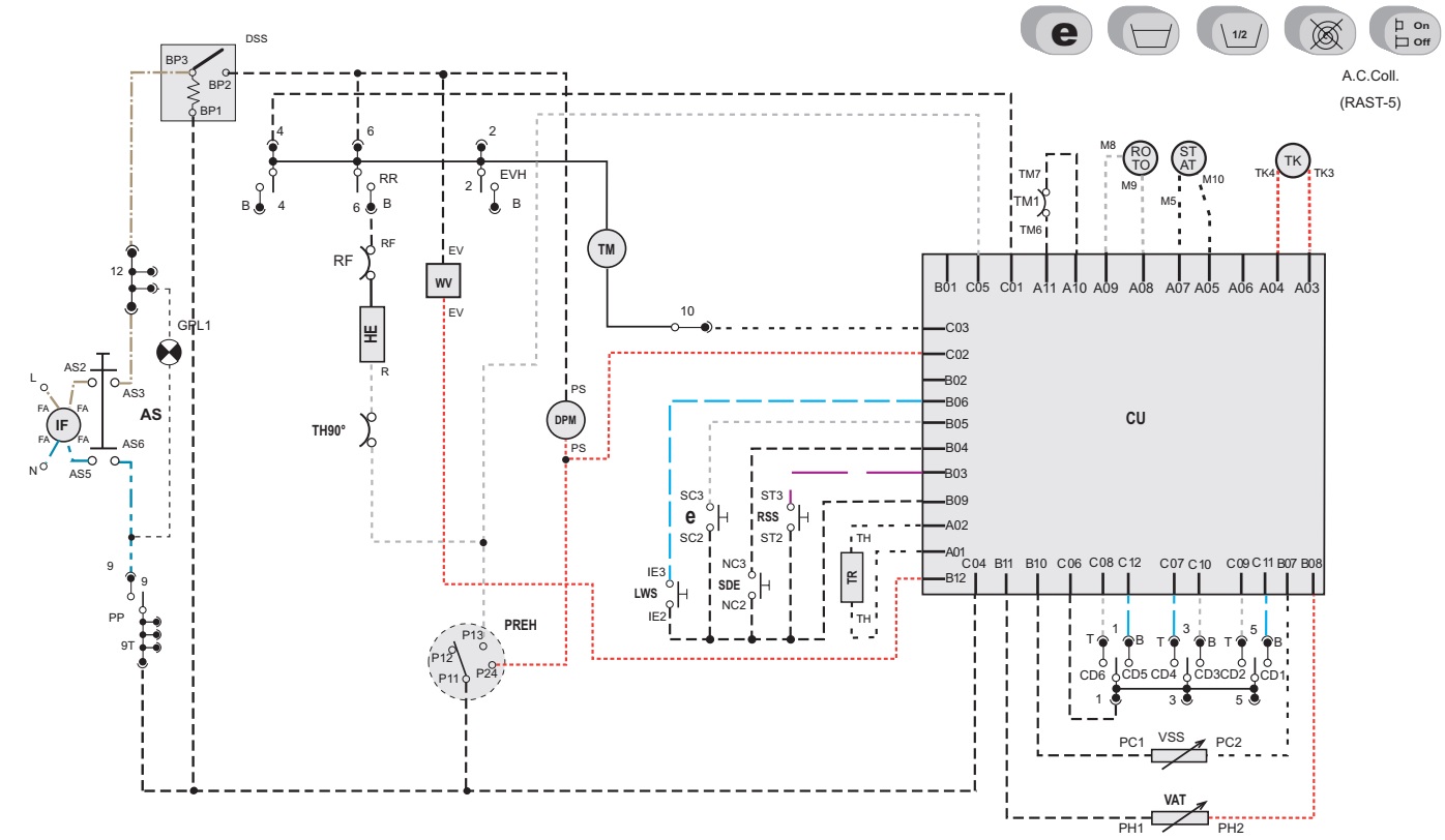
Washing machine - Ardo TL1000, Ardo CO3012SA - error codes, reset, schematic


Ardo washing machine error codes, reset procedure, main board schematic
Error codes 
E00,E01: Drain from washing machine.
E02: Incorrect Drain / Fill of water and spin, incorrect drain hose position.[System malfunction]
E03: no discharge of water from the tank or the drainage time has been exceeded [more than three minutes]
A technical malfunction which in any case should be addressed to the service center.
F2: Temperature Sensor problems in the control module or with the heating element.
F4: malfunction in the drain pump.  Need replacement.
F5:  simultaneous drain and set of water.  The drain hose is not properly connected or there are problems in the water supply filter.
F6, F12: water overflow in the tank. Module or motor malfunction.
F8: excessive water level in the tank.  Water level sensor problem. Solenoid valve should be checked.
F13, F14:  water level sensor problem with solenoid valve.
Reset [A-Models]
By pressing the “Off “button, wait for at least one minute, and then press the “On” button.
Reset the control panel by Hold down the “Back” and “My Cycles” buttons simultaneously for three seconds, and then release both the buttons.
Write down any errors displayed in case the washing machine ultimately needs a service call,  if the word “More” is displayed, press the “More” to identify the rest of the errors. To exit, press “Exit”.
Unplug the machine and plug back.
Press the ‘Power” button and the “Start/Stop” button simultaneously  the machine powers ON, the Home screen pops up, signaling theat the machine is alright.
Ardo CO3012SA schematic
Ardo TL1000 schematic
Reset [B-Models]
Unplug the machine for 30 seconds.
Plug it back, and after 30 seconds push the “Pause/Cancel/Stop” button two times and choose a wash cycle.
Press the “Start” button until wash cycle begins, to ensure that the machine is functioning well.
To reset the error message.
To cancel the message, turn the rotary selector to “Stop/End” or press the “Start/Stop” switch for 5 seconds. Then switch the machine Off and back On again.  If the fault message reappears again, take off the service panel button on the red-brown heater located on the left side.

Thursday, 13 June 2019

SHARP TU-R160H-TU-R162H-TU-R252H PVR TROUBLESHOOTING AND POWER SUPPLY SCHEMATIC DIAGRAM

Troubleshooting
Problem
The picture is freezing during live TV or playback recording
The picture is skipping during live TV or playback recording
The picture is blocking (Pixelated) during live TV or playback recording
The channel I am watching is working, but the PIP or recording I have made is exhibiting the faults mentioned
Solution
There could be many reasons for this fault.
Follow the guidelines provided below.
Signal Problem
The first item to check is that you are in an area that receives a Freeview signal.
The Freeview signal cover 97% of the United Kingdom, but there are variations in the channels that you can receive.
Example:
If you live in the Manchester area, postcode M40 5BE, you are able to receive the whole family of Freeview channels.
If you live in the Worcestershire area, postcode WR9 8JB, you are able to receive some of the Freeview channels.
Note: A signal related fault is not a fault with your Sharp DTR.
If you contact the Sharp DTR helpline, we will be unable to deal with your request. Signal related problems should be dealt with by your retailer or via an approved aerial installation company. In most cases, skipping / freezing / blocking is caused by a reception problem - either the signal is too weak or there is some kind of interference.
Example:
The first tuner in the Sharp Freeview recorder will receive the signal at the same level quality as your single tuner Freeview box.
The second tuner in the Sharp Freeview recorder will receive the signal at a slight reduction of 0.5dB less than the first tuner.
If you are receiving a borderline signal, this may result in your PIP or recording skipping / freezing / blocking.
In rare cases, skipping / freezing / blocking is caused by a reception problem - the signal is too strong.
Example:
If you are living in an area that receives a signal from the Crystal Palace transmitter or if you are positioned very close to the transmitter.
The final cause of your problem is the channel you are watching is working, but the PIP or recording is skipping / freezing / blocking.
Example:
I am watching BBC1, but my recording from Channel FIVE is skipping / freezing / blocking. This is caused by the variation in signal strength between the different multiplexes. Different channels are located on different multiplexes.
Hard Disk Malfunction
On rare occasions the Hard Disk may malfunction, in most cases formatting the Hard Disk will restore normal operation however ALL the data stored on the Hard Disk will be lost. Ensure you dub important recordings onto Video or DVD before you format the HDD.
Press the “Menu” button on the remote control.
Using the cursor arrows on the remote control, select “SETUP”.
Using the cursor arrows on the remote control, select “RECORDINGS”
Press OK when the “Format Disk” option is highlighted.
A menu appears, in which you will be asked for a pin number. If you have not changed the pin number, the factory default is 0000.
After you enter the pin number, a pop-up menu appears on the screen to ensure that the hard disk should be formatted.
Select "YES" and press OK to format the Hard Disk. Select "NO" and press OK to cancel.
Displays “ STARTING “ and No function.
CAUSE
Software issues.
ACTION
Download the latest software from the TechWeb site and update the operating software in the receiver.
To Upload the saved firmware to this unit follow these procedures
1. Unplug the TUR from the mains supply.
2. Connect your PC to the TUR using a straight through serial cable.
3. Open Hyperterminal on your PC (Can be found in Accessories, Connectivity).
4. Set your COMs port settings to BPS 115200, DB 8, Parity Non, SB 1, FC Non.
5. Click Transfer, Send File.
6. Select the attached file from the location where you have downloaded it on your PC and change the protocol to 1K Xmodem.
7. Click Send, then plug the TUR into the mains.
8. The firmware should start downloading to the unit, this takes aprx 3 minutes
9. Once the TUR displays an image, the firmware upload is complete.
STRW62521
Description
STR-W6200D series are power ICs for switching power supplies, incorporating a power MOSFET and a current mode PWM controller IC in one package. Including a startup circuit and a standby function in the controller, the product achieves low power consumption, low standby power, and high cost-effectiveness in power supply systems, while reducing external components.
POWER SUPPLY CIRCUIT 

Monday, 10 June 2019

YAMAHA AV RECEIVER RX-V2065 - HTR-6295 – Firmware update – Self diagnostics – Protection mode


 YAMAHA RX-V2065 - HTR-6295 - UPDATING FIRMWARE
Confirmation of firmware version and checksum
Before and after writing firmware, check the firmware version and checksum by using the self-diagnostic function menu.
Start up the self-diagnostic function and select “25. ROM VER/SUM/PORT” menu. (See “SELF-DIAGNOSTIC FUNCTION”)
Using the sub-menu, have the firmware version and checksum displayed, and note down them.
Supplementary information:
In this unit, it is possible to check the firmware version by using the ADVANCED SETUP menu as well as the self-diagnostic function menu. Follow the procedures below.
1. While pressing the “STRAIGHT” key of this unit, press the “MAIN ZONE ON/OFF” key of this unit to turn on the power.
The ADVANCED SETUP mode is activated, and “ADVANCED SETUP” is displayed.
2. Rotate the “PROGRAM” knob and select the “VER---.---.---” After a few seconds, each firmware version is displayed.
3. Press the “MAIN ZONE ON/OFF” key of this unit to turn off the power.
Writing method using the USB
Required Tools
# USB storage device
# Firmware RX-V2065 : RX-V2065_xxxx.bin
HTR-6295 : HTR-6295_xxxx.bin
# Preparation
1. Download the latest firmware from the specified download source to the folder of the PC.
2. Copy the latest firmware from the PC to the root folder of the USB storage device.
Note: When the firmware is copied to a sub-folder of the USB storage device, the update will not proceed.
# Operation procedures
1. Insert the USB storage device to the USB terminal located on the front panel of this unit.
2. While pressing the “TONE CONTROL” key of this unit,  connect the power cable to the AC outlet.  Writing of the firmware is started and the screen is displayed as shown below.
3. When writing of the firmware is completed, “UPDATE SUCCESS” is displayed.
* When “UPDATE FAIL” is displayed before writing is completed, perform the operation procedures from step 1 to 2 again.
4. Press the “MAIN ZONE ON/OFF” key of this unit to turn off the power.
5. Remove the USB storage device from the USB terminal of this unit.
6. Start up the self-diagnostic function and select “25. ROM VER/SUM/PORT” menu.
Using the sub-menu, have the firmware version and checksum displayed, and then check that they are the same as
written ones.
* When the displayed firmware version and checksum are different from written ones, perform the “Writing the Firmware” procedure all over again.
7. Press the “MAIN ZONE ON/OFF” key to turn off the power.
Writing method using PC (RS232C)
Required Tools
# Firmware down loader program
For main microprocessor:
DSP_FLASHER_v3.0.exe
For DSP (TI flash ROM):
DSP_FLASHER Ver2.7.exe
# Firmware
For main microprocessor: V265xxxx.mot
For DSP (TI flash ROM):
Vx65_data1_verxxxxxr.hex
Preparation and precautions
# Download the firmware downloader program and the firmware from the specified source to the same folder of the PC.
# Prepare the above specified RS232C cross cable.
# while writing the firmware, keep the other application software on the PC closed.
It is also recommended to keep the software on
the task tray closed as well.
# Connection
1. Remove the top cover.
2. Connect the writing port (CB27 of DIGITAL P.C.B.) of this unit to the serial port (RS232C) of the PC with RS232C cross cable, RS232C conversion adaptor and flexible flat cable.
3. Set the switch (SW7) of RS232C conversion adaptor.
# RS232C conversion adaptor (Part No.: WR492800)
Writing to the main microprocessor
1. With the power cable of this unit disconnected from the AC outlet, start up DSP_FLASHER_v3.0.exe.
The screen appears as shown below.
2. Click [Brows] and select the firmware name.
3. Connect the power cable of this unit to the AC outlet.
4. Click [E.P.] to start writing.
5. When writing of the firmware is completed, “Program Finished!” is displayed.  Click [OK].
6. Click [EXIT] to end DSP_FLASHER_v3.0.exe.
7. Disconnect the power cable of this unit from the AC outlet.
8. Remove the RS232C conversion adaptor and flexible flat cable from the writing port (CB27, DIGITAL P.C.B.) of this unit.
9. Start up the self-diagnostic function and select “25.ROM VER/SUM/PORT” menu. Using the sub-menu, have the firmware version and checksum displayed, and then check that they are the same as written ones.
* If  the firmware version and checksum are different from written ones, perform the “Writing to the microprocessor” all over again.
10. Press the “MAIN ZONE ON/OFF” key of this unit to turn off the power.
11. Disconnect the power cable of this unit from the AC outlet.
Writing to DSP
1. With the power cable of this unit disconnected from the AC outlet, start up DSP_FLASHER Ver2.7.exe.
The screen appears as shown below.
2. Click [Vx61 DSP].
3. Click [Brows] and select the firmware name.
4. Click [RDY].
5. While pressing the “PURE DIRECT” key of this unit, connect the power cable of this unit to the AC outlet.  Writing is started automatically.
6. When writing of the firmware is completed, “Vx61 DSP Flash finished!” is displayed.
7. Click [EXIT] to end DSP_FLASHER_v2.7.exe.
8. Start up the self-diagnostic function and select “25.ROM VER/SUM/PORT” menu.
Using the sub-menu, have the firmware version and checksum displayed, and then check that they are the same as written ones.
* If the firmware version and checksum are different from written ones, perform the “Writing to DSP” all over again.
9. Press the “MAIN ZONE ON/OFF” key of this unit to turn off the power.
10. Disconnect the power cable of this unit from the AC outlet.
11. Remove the RS232C conversion adaptor and flexible flat cable from the writing port (CB27, DIGITAL P.C.B.) of this unit.
Starting Self-Diagnostic Function
While pressing TONE CONTROL and PURE DIRECT in the unit, press the “MAIN ZONE ON/OFF” key to turn on the power.
The self-diagnostic function mode is activated.
Starting Self-Diagnostic Function in the protection cancel mode
If the protection function works and causes hindrance to trouble shoot, cancel the protection function as described below, and it will be possible to enter the self-diagnostic function mode.
(The protection functions other than the excess current detect function will be disabled.)
While pressing those 2 keys as shown in the figure above, press the “MAIN ZONE ON/OFF” key to turn on the power and keep pressing those 2 keys and “MAIN ZONE ON/OFF” key for 3 seconds or longer.
The self-diagnostic function mode is activated with the protection functions disabled.
In this mode, the SLEEP segment of the FL display of this unit flashes to indicate that the mode is self-diagnostic function mode with the protection functions disabled.
Canceling Self-Diagnostic Function
1. Before cancelling self-diagnostic function, execute setting for FACTORY PRESET of main menu No. 24 (Memory initialisation inhibited or Memory initialised).
* In order to keep the user memory stored, be sure to select PRESET INHIBITED (Memory initialisation inhibited).
2. Press the “MAIN ZONE ON/OFF” key of this unit to turn off the power.
Display provided when Self-Diagnostic Function started
The display is as described below depending on the situation when the last time the power to this unit is turned off.
When the power is turned off by usual operation:
The FL display of this unit displays “NO PROTECT” then the main menu (sub-menu “1. ANALOG BYPAS” of main menu 1 BYPASS) a few seconds later.
When the protection function worked to turn off the power
The FL display of this unit displays the data of protection function which worked at that time then the main menu (sub-menu “1.
ANALOG BYPAS” of main menu 1 BYPASS) a few seconds later.
Note: At that time if you reactivate the self-diagnostic function after turning off the power once by pressing the “MAIN
ZONE ON/OFF” key, “NO PROTECT” will be displayed because that situation is equal to “1. When the power is turned off by usual operation:” described above.
However the protection function history is stored in a backup memory. For details, refer to main menu 21 PROTECTION HISTORY.
When the protection function worked due to excess current
Cause: An excessive current flowed through the power amplifier.
Supplementary information: As current of the power amplifier is detected, the abnormal channel can be identified by
checking the current detect transistor.
Turning on the power without correcting the abnormality will cause the protection function to work immediately and the
power supply will instantly be shut off.
Note:  Applying the power to this unit without correcting the abnormality can be dangerous and cause additional circuit damage. To avoid this, if protection function has been activated 3 times continuously, the power will not turn on even when the “MAIN ZONE ON/OFF” key is pressed. In order to turn on the power again, disconnect the power cable of this unit from the AC outlet once and then reconnect it again.
#
The output transistors in each amplifier channel should be checked for damage before applying power of this unit.
Amplifier current should be monitored by measuring DC voltage across the emitter resistors for each channel.
When the protection function worked due to a short between speaker terminals
Cause: The line between speaker terminals is shorted.
Supplementary information: As the excess current is detected after operation of the speaker relay, the shorted speaker
terminal and the connected speaker can be identified.
Turning on the power without correcting the abnormality will cause the protection function to work immediately and the
power supply will instantly be shut off.
When the protection function worked due to abnormal DC output
Cause: DC output from the power amplifier is abnormal.
Supplementary information: The protection function worked due to a DC voltage appearing at the speaker terminal. A cause could be a defect in the amplifier.
Turning on the power without correcting the abnormality will cause the protection function to work in 3 seconds and the power supply will be shut off.
When the protection function worked due to abnormal voltage in the power supply section
Cause: The voltage in the power supply section is abnormal.
Supplementary information: The protection function worked due to a defect or overload in the power supply.
Turning on the power without correcting the abnormality will cause the protection function to work in 1 second and the power supply will be shut off.
When the protection function worked due to excessive heat sink temperature
Cause: The temperature on the heat sink is excessive.
Supplementary information: The protection function worked due to the temperature limit being exceeded.
Causes could be poor ventilation or a defect related to the thermal sensor.
Turning on the power without correcting the abnormality will cause the protection function to work in 1 second and the power supply will be shut off.
History of protection function
When the protection function has worked, its history is stored in memory with a backup.
Even if no abnormality is noted while servicing the unit, an abnormality which has occurred previously can be defined as long as the backup data has been stored.
For details of the history of protection function, refer to main menu 21 PROTECTION HISTORY.
The history of the protection function is cleared when self-diagnostic function is cancelled by selecting PRESET RESERVED (Memory initialised) of main menu 24 or when the backup data is erased.

LG 32LK610BPUA, LG 32LK610BBUA LCD TVs – How to upgrade the software, fault checking method

  Software update procedure USB (1) Insert the USB memory Stick to the USB port (2) Automatically detect the SW Version and show the bel...