Tuesday, 19 June 2018

Apple iPod Shuffle – Disassembling procedure – How to remove the case – How to remove the Battery


Apple iPod Shuffle:  DISASSEMBLING PROCEDURE 
Before beginning, be sure your Shuffle is turned off as shown.
Use the edge of an iPod opening tool to pry the plastic cover off the headphone jack side of the Shuffle.
Remove the plastic cover and set it aside.
Remove the two Phillips screws from the headphone jack side of the Shuffle.
Use the edge of an iPod opening tool to remove the steel cover from the headphone jack side of the Shuffle.
Use the edge of an iPod opening tool to pry the plastic cover off the controls side of the Shuffle. Remove the plastic cover and set it aside.
Use a pair of tweezers to remove the hold and shuffle sliders from the Shuffle.
Remove the two Phillips screws on the controls side of the Shuffle.
Use the edge of an iPod opening tool to remove the steel plate from the controls side of the Shuffle.
Use the edge of an iPod opening tool to slightly pry the steel plate on the headphone jack side of the Shuffle away from the lip cut into the outer case.
Use your iPod opening tool to push the logic board assembly out of the outer case enough to grab the logic board by its edges. Pull the logic board assembly out of the outer case.
Use the edge of an iPod opening tool to peel the adhesive under the battery that secures it to the logic board.
Flip the battery upwards to reveal the solder pads soldered to the logic board. Before desoldering the battery, be sure to scrape the protective resin off both solder points.
Desolder the battery from the logic board by heating up the solder joint with a soldering iron and simultaneously using a pair of tweezers to pull the battery wire away from the logic board.Do not touch the + and - leads together.

Saturday, 16 June 2018

Apple iPhone 6 – How to replace the display shield of Apple iPhine 6 Apple iPhone 6


Display shield replacement procedure
Power off your iPhone before beginning disassembly. Remove the two 3.6 mm Pentalobe screws next to the Lightning connector.
The next three steps demonstrate using the iSclack, a great tool for safely opening the iPhone 6 that we recommend for anyone doing more than one repair. If the plastic depth gauge is attached at the center of the iSclack, remove it now it's not needed for larger phones like the iPhone 6. Close the handle on the iSclack, opening the suction-cup jaws.
Place the bottom of your iPhone in between the suction cups. Position the iSclack's upper suction cup against the display, just above (but not covering) the home button.
Open the handles to close the jaws of the iSclack. Center the suction cups and press them
firmly onto the top and bottom of the iPhone.
Hold onto your iPhone securely and close the handle of the iSclack to separate the suction cups, pulling the front panel up from the rear case. The iSclack is designed to safely open your iPhone just enough to separate the pieces, but not enough to damage the display cables. Peel the two suction cups off your iPhone.
Front Panel Assembly
If you don't have an iSclack, use a single suction cup to lift the front panel: Press a suction cup onto the screen, just above the home button.
Be sure the cup is pressed securely onto the screen to get a tight seal.While holding the iPhone down with one hand, pull up on the suction cup to slightly separate the front panel assembly from the rear case. Take your time and apply firm, constant force. The display assembly is a much tighter fit than most devices.
Using a plastic opening tool, begin to gently pry the rear case down, away from the display assembly, while continuing to pull up with the suction cup.
There are several clips holding the front panel assembly to the rear case, so you may need to use a combination of the suction cup and plastic opening tool to free the front panel assembly.
Pull the plastic nub to release the vacuum seal on the suction cup.
Remove the suction cup from the display assembly.
Pull the home button end of the front panel assembly away from the rear case, using the top of the phone as a hinge.
Keep the front panel supported at a 90º angle in relation to the rear case until you remove it allowing it to fall flat will strain the display cables and their connections on the logic board.
Several clips along the top edge of the front panel form a partial hinge, allowing the front panel assembly to swing open like a book. During reassembly, align the clips just below the top edge of the rear case. Then, slide the front panel upward until its top edge is flush with that of the rear case.
Remove the following five Phillips screws securing the front panel assembly cable bracket:
Three 1.2 mm screws
One 1.7 mm screw
One 3.1 mm screw
Remove the front panel assembly cable bracket from the logic board.
In the next four steps, take care to pry up only on the cable connectors, and not on their sockets on the logic board.
Use the flat end of a spudger to disconnect the front-facing camera and sensor cable connector.
Use the flat end of a spudger to disconnect the home button cable connector.
Use the flat end of a spudger to disconnect the display data cable connector. When reassembling your phone, the display data cable may pop off its connector. This can result in white lines or a blank screen when powering your phone back on. If that happens, simply reconnect the cable and power cycle your phone. The best way to power cycle your phone is to disconnect and reconnect the battery connector.
Use the flat end of a spudger to disconnect the digitizer cable connector.
Remove the front panel assembly from the rear case.
Remove the two 1.9 mm Phillips #00 screws securing the home button bracket.
Remove the home button bracket from the front panel.
Use the point of a spudger to disconnect the home button cable connector by pushing it up and away from the home button.
Remove the following Phillips #00 screws securing the LCD shield plate to the front panel:
One 1.7 mm screw
Six 1.6 mm screws (three on each side)
Lift the front-facing camera end of the LCD shield plate up slightly. Do not attempt to remove the shield plate entirely, it is still attached to the front panel via home button cable.
Slide the point of a spudger behind the shield plate to gently lift the home button cable up off of the front panel.
Remove the LCD shield plate.
Peel the black backing tape away from the home button cable. You may need tweezers to start peeling, however the tape is brittle and it may be hard to complete the job with tweezers alone.
Carefully peel the home button cable up off of the adhesive holding it to the LCD shield plate.

Thursday, 14 June 2018

Lenovo ideapad 310 – AC adapter testing procedure – How to remove the key board – How to test the babttrey pack


Lenovo ideapad 310:  To verify a symptom, follow the steps below:
1. Turn off the computer.
2. Remove the battery pack.
3. Connect the AC adapter.
4. Make sure that power is supplied when you turn on the computer.
5. Turn off the computer.
6. Disconnect the AC adapter and install the charged battery pack.
7. Make sure that the battery pack supplies power when you turn on the computer.
If you suspect a power problem, see the appropriate one of the following power supply checkouts:
“Checking the AC adapter”
“Checking operational charging”
“Checking the battery pack”
Checking the AC adapter
You are here because the computer fails only when the AC adapter is used.
If the power-on indicator does not turn on, check the power cord of the AC adapter for correct continuity and installation.
To check the AC adapter, follow the steps below:
1. Unplug the AC adapter cable from the computer.
2. Measure the output voltage at the plug of the AC adapter cable. See the following figure:
Note: Output voltage for the AC adapter pin No. 2 may differ from the one you are servicing.
3. If the voltage is not correct, replace the AC adapter.
4. If the voltage is acceptable, do the following:
Replace the system board.
Note: Noise from the AC adapter does not always indicate a defect.
Checking operational charging
To check whether the battery charges properly during operation, use a discharged battery pack or a battery pack that has less than 50% of the total power remaining when installed in the computer.
Perform operational charging. If the battery status indicator or icon does not light on, remove the battery pack and let it return to room temperature. Reinstall the battery pack. If the charge indicator or icon is still off, replace the battery pack.
If the charge indicator still does not light on, replace the system board. Then reinstall the battery pack. If it is still not charged, go to the next section.
Checking the battery pack
Battery charging does not start until the Power Meter shows that less than 95% of the total power remains; under this condition the battery pack can charge to 100% of its capacity. This protects the battery pack from being overcharged or from having a shortened life.
To check your battery, move your cursor to the Power Meter icon in the icon tray of the Windows  taskbar and wait for a moment (but do not click it), and the percentage of battery power remaining is displayed. To get detailed information about the battery, double-click the Power Meter icon.
Note: If the battery pack becomes hot, it may not be able to be charged. Remove it from the computer and leave it at room temperature for a while. After it cools down, reinstall and recharge it.
DISASSEMBLING PROCEDURE 
Hard disk drive(HDD) slot compartment cover
Remove the screw 1 that secure the compartment cover. Remove the compartment cover
Memory/Mini PCI Express Card slot compartment cover and DIMM
Remove the screw that secure the compartment cover1. Remove the compartment cover
Release the two latches on both edges of the socket at the same time in the direction shown by arrows 3, and then unplug the DIMM
Remove screws
Pull the touch pad connector and keyboard connector slot cover upward as shown by arrow 2, and detach the touch pad board cable and keyboard cable from the touch pad board connector and keyboard connector
When installing: Make sure that the FPC connectors are attached firmly. Remove the keyboard bezel

Lenovo G70-70 - G70-80 – Disassembling procedure – How to remove the keyboard – How to test the ac adapter – How to check the battery pack


Lenovo G70-70 - G70-80:  To verify a symptom, follow the steps below:
1. Turn off the computer.
2. Remove the battery pack.
3. Connect the AC adapter.
4. Make sure that power is supplied when you turn on the computer.
5. Turn off the computer.
6. Disconnect the AC adapter and install the charged battery pack.
7. Make sure that the battery pack supplies power when you turn on the computer.
If you suspect a power problem, see the appropriate one of the following power supply checkouts:
“Checking the AC adapter”
“Checking operational charging”
“Checking the battery pack”
Checking the AC adapter
You are here because the computer fails only when the AC adapter is used.
 If the power-on indicator does not turn on, check the power cord of the AC adapter for correct continuity and installation.
To check the AC adapter, follow the steps below:
1. Unplug the AC adapter cable from the computer.
2. Measure the output voltage at the plug of the AC adapter cable. See the following figure:
Note: Output voltage for the AC adapter pin No. 2 may differ from the one you are servicing.
3. If the voltage is not correct, replace the AC adapter.
4. If the voltage is acceptable, do the following:
Replace the system board.
Note: Noise from the AC adapter does not always indicate a defect.
Checking operational charging
To check whether the battery charges properly during operation, use a discharged battery pack or a battery pack that has less than 50% of the total power remaining when installed in the computer.
Perform operational charging. If the battery status indicator or icon does not light on, remove the battery pack and let it return to room temperature. Reinstall the battery pack. If the charge indicator or icon is still off, replace the battery pack.
If the charge indicator still does not light on, replace the system board. Then reinstall the battery pack. If it is still not charged, go to the next section.
Checking the battery pack
Battery charging does not start until the Power Meter shows that less than 95% of the total power remains; under this condition the battery pack can charge to 100% of its capacity. This protects the battery pack from being overcharged or from having a shortened life.
To check your battery, move your cursor to the Power Meter icon in the icon tray of the Windows taskbar and wait for a moment (but do not click it), and the percentage of battery power remaining is displayed. To get detailed information about the battery, double-click the Power Meter icon.
Note: If the battery pack becomes hot, it may not be able to be charged. Remove it from the computer and leave it at room temperature for a while. After it cools down, reinstall and recharge it.
DISASSEMBLING PROCEDURE 
Battery pack
Unlock the manual battery latch .1 Slide the spring-loaded latch to the unlocked position to eject the battery pack 2. Lift up the inner edge of the battery pack, pivoting it on the outer edge 3. Slide the battery pack in the indicated direction to remove it 4.
Keyboard
Remove the screws 1.
Push the back of the keyboard in the direction shown by the arrow.
Loosen the keyboard with fingers in the direction shown by arrow 2.
Lift the keyboard a little 3 . Pull the keyboard connector slot cover upward as shown by arrow 4, and detach the keyboard cable from the keyboard connector in the direction shown by arrow 5.
Lenovo ThinkPad T440s – Business Ultabook laptop - AC adapter Voltage testing procedure – Backup battery testing – Back cover removal To replace the built in battery -  Key board removal – Diagnostic program -  Laptop repair and service

Lenovo IdeaPad - U330p - U330 – Disassembling procedure – How to test the charger – how to check the battery pack – How to remove battery


Lenovo IdeaPad - U330p - U330:  To verify a symptom, follow the steps below:
1. Turn off the computer.
2. Remove the battery pack.
3. Connect the AC adapter.
4. Make sure that power is supplied when you turn on the computer.
5. Turn off the computer.
6. Disconnect the AC adapter and install the charged battery pack.
7. Make sure that the battery pack supplies power when you turn on the computer.
If you suspect a power problem, see the appropriate one of the following power supply checkouts:
“Checking the AC adapter”
“Checking operational charging”
“Checking the battery pack”
Checking the AC adapter
You are here because the computer fails only when the AC adapter is used.
If the power-on indicator does not turn on, check the power cord of the AC adapter for correct continuity and installation.
If the computer does not charge during operation, go to “Checking operational charging”.
To check the AC adapter, follow the steps below:
1. Unplug the AC adapter cable from the computer.
2. Measure the output voltage at the plug of the AC adapter cable. See the following figure:
Note: Output voltage for the AC adapter pin No. 2 may differ from the one you are servicing.
3. If the voltage is not correct, replace the AC adapter.
4. If the voltage is acceptable, do the following:
Replace the system board.
Note: Noise from the AC adapter does not always indicate a defect.
Checking operational charging
To check whether the battery charges properly during operation, use a discharged battery pack or a battery pack that has less than 50% of the total power remaining when installed in the computer.
Perform operational charging. If the battery status indicator or icon does not light on, remove the battery pack and let it return to room temperature. Reinstall the battery pack. If the charge indicator or icon is still off, replace the battery pack.
If the charge indicator still does not light on, replace the system board.Then reinstall the battery pack. If it is still not charged, go to the next section.
Checking the battery pack
Battery charging does not start until the Power Meter shows that less than 95% of the total power remains; under this condition the battery pack can charge to 100% of its capacity. This protects the battery pack from being overcharged or from having a shortened life.
To check your battery, move your cursor to the Power Meter icon in the icon tray of the Windows  taskbar and wait for a moment (but do not click it), and the percentage of battery power remaining is displayed. To get detailed information about the battery, double-click the Power Meter icon.
Note: If the battery pack becomes hot, it may not be able to be charged. Remove it from the computer and leave it at room temperature for a while. After it cools down, reinstall and recharge it.
DISASSEMBLING PROCEDURE 
How to remove Battery pack
Remove ten screws 1 and two screws 2.
Open the back cover in the direction shown by arrow 3.
How to remove Hard disk drive
Remove the frame fixing screws 1. Pull the tab in the direction shown by arrow 2.
Hold the SATA receptacle connector with one hand and pull the hard disk drive (secured in the metal frame) in the direction shown below to detach the connector.

Lenovo IdeaPad S10-3s – How to test the battery charger – How to test the battery pack – How to remove the keyboard


1. Turn off the computer.
2. Remove the battery pack.
3. Connect the AC adapter.
4. Make sure that power is supplied when you turn on the computer.
5. Turn off the computer.
6. Disconnect the AC adapter and install the charged battery pack.
7. Make sure that the battery pack supplies power when you turn on the computer.
If you suspect a power problem, see the appropriate one of the following power
supply checkouts:
“Checking the AC adapter ”
“Checking operational charging”
“Checking the battery pack ”
Checking the AC adapter
You are here because the computer fails only when the AC adapter is used.
If the power-on indicator does not turn on, check the power cord of the AC adapter for correct continuity and installation.
To check the AC adapter, follow the steps below:
1. Unplug the AC adapter cable from the computer.
2. Measure the output voltage at the plug of the AC adapter cable. See the following figure:
Note: Output voltage for the AC adapter pin No. 2 may differ from the one you are servicing.
3. If the voltage is not correct, replace the AC adapter.
4. If the voltage is acceptable, do the following:
Replace the system board.
Note: Noise from the AC adapter does not always indicate a defect.
Checking operational charging
To check whether the battery charges properly during operation, use a discharged battery pack or a battery pack that has less than 50% of the total power remaining when installed in the computer.
Perform operational charging. If the battery status indicator or icon does not light on, remove the battery pack and let it return to room temperature. Reinstall the battery pack. If the charge indicator or icon is still off, replace the battery pack.
If the charge indicator still does not light on, replace the system board. Then reinstall the battery pack. If it is still not charged, go to the next section.
Checking the battery pack
Battery charging does not start until the Power Meter shows that less than 95% of the total power remains; under this condition the battery pack can charge to 100% of its capacity. This protects the battery pack from being overcharged or from having a shortened life.
To check your battery, move your cursor to the Power Meter icon in the icon tray of the Windows taskbar and wait for a moment (but do not click it), and the percentage of battery power remaining is displayed. To get detailed information about the battery, double-click the Power Meter icon.
Note: If the battery pack becomes hot, it may not be able to be charged. Remove it from the computer and leave it at room temperature for a while. After it cools down, reinstall and recharge it.
To check the battery pack, follow the steps below:
1. Turn off the computer.
2. Remove the battery pack and measure the voltage between battery terminals 1 (+) and 7 (-). See the following figure:
3. If the voltage is less than +11.0 V DC, the battery pack has been discharged.
Note: Recharging will be continued for at least 3 hours, even though the indicator does not light on. If the voltage is still less than +11.0 V DC after recharging, replace the battery.
4. If the voltage is more than +11.0 V DC, measure the resistance between battery terminals 5 and 7. The resistance must be 4 to 30 KΩ. If the resistance is not correct, replace the battery pack. If the resistance is correct, replace the system board.
Restore of factory default
The IdeaPad S10-3s computers come with pre-installed OneKey Rescue System. In order to save application files and the initial backed up files of the system, the hard disk in a Lenovo computer includes a hidden partition when it is shipped. If you need to restore the system to the point of your first boot up, just enter Lenovo OneKey Rescue System and run Restore to factory default.
DISASSEMBLING PARTS 
Battery pack
Unlock the battery release lever 1. Holding the battery release lever in the unlocked position 2, remove the battery pack in the direction shown by arrow 3.
Keyboard
Remove three screws 1.
Lift the keyboard a little, detach the connector in the direction shown by arrows 2 3, and then remove the keyboard 4.

How to Replace the case of Apple Mac Mini


Apple Mac Mini:  CASE REPLACEMENT PROCEDURE 
Place your thumbs in the depressions cut into the bottom cover.
Rotate the bottom cover counter-clockwise until the white dot painted on the bottom cover is aligned with the ring inscribed on the outer case.
Tilt the mini enough to allow the bottom cover to fall away from the outer case.
Remove the bottom cover and set it aside.
Remove the two 11.3 mm T6 Torx screws securing the fan to the logic board near the antenna plate.
Lift the ear of the fan nearest the RAM up off the standoff secured to the outer case.
Lift the fan out of the mini for enough clearance to access its connector. Carefully pull the fan cables upward to lift the fan connector up out of its socket on the logic board. Remove the fan.
Remove the single 3.5 mm T6 Torx screw securing the cowling to the heat sink.
Lift the cowling from the end nearest the antenna plate.
Rotate the cowling away from the outer case and remove it from the mini.
Remove the following screws securing the antenna plate to the mini:
Two 6.6 mm T8 Torx screws
Two 5.0 mm T8 Torx or 2.0 mm
Hex screws (either will work)
Slightly lift the antenna plate from the end closest to the RAM.
Carefully pull the antenna plate straight away from the circular rim of the outer case.
Do not remove the antenna plate yet. It is still attached to the AirPort/ Bluetooth board.
Use the tip of a spudger to carefully pry the antenna connector up off the AirPort/Bluetooth board.
Remove the antenna plate from the mini.
Remove the following three screws: One 5.0 mm T8 Torx or 2.0 mm Hex screw (either will work)
One 16.2 mm T6 Torx screw
One 26 mm T6 Torx standoff
Carefully pull the wires for both hard drive thermal sensors upward to lift their connectors up and out of the sockets on the logic board.
Use the flat end of a spudger to pry both the hard drive and optical drive connectors up out of their sockets on the logic board.
To disconnect the optical drive thermal sensor, pinch its cables between your thumb and a spudger and pry the spudger upward to lift the connector up and out of its socket on the logic board.
Use the tip of a spudger to lift the IR sensor connector up and out of its socket on the logic board.
To remove the logic board, two cylindrical rods must be inserted into the holes highlighted in red. Inserting instruments into any logic board holes other than the ones highlighted in red may destroy the logic board.
Insert a Mac Mini Logic Board Removal Tool into the two holes highlighted in red. Be sure it makes contact with the outer case below the logic board before proceeding.
If you don't have a Logic Board Removal Tool handy, you can use two tools having a maximum diameter of 2.5 mm instead. Just insert one into each of the highlighted holes.
Carefully pull the tool toward the I/O board. The logic board and I/O board assembly should slightly slide out of the outer case.
Cease prying when the I/O board is visibly separated from the outer case. Remove the Mac Mini Logic Board Removal tool.
Simultaneously push the two plastic clips on the far left and right sides of the I/O board toward the middle of the I/O board and pull the I/O board away from the outer case.
Pull the I/O board/logic board assembly out of the outer case enough to access the power connector.
Use a pair of tweezers to disconnect the power cable from the logic board.
Pull the power cable connector toward the optical drive opening.
Carefully slide the logic board assembly out of the mini, minding any cables that may get caught.
Remove the 7.9 mm T6 Torx screw securing the power supply and optical drive to the outer case.
Pull the silver metal AC-In socket retainer away from the side of the outer case and remove it from the mini.
Rotate the AC-In connector 90 degrees counter-clockwise.
Slide the power supply out of the mini, minding any cables that may get caught.
Remove the hard drive from the mini, minding any cables that may get caught.
Remove the 7.9 mm T6 Torx screw securing the optical drive to the outer case.
Slide the optical drive out of the outer case, minding any cables that may get caught.

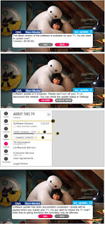
LG 32LK610BPUA, LG 32LK610BBUA LCD TVs – How to upgrade the software, fault checking method

  Software update procedure USB (1) Insert the USB memory Stick to the USB port (2) Automatically detect the SW Version and show the bel...