Sunday, 30 May 2021

LG COLOR MONITOR Flatron 24EA53Q (24EA53VQ-*A)- LM13E chassis 24 inch color monitor – how to enter the service mode, schematic, how to disassemble


 TFT Colour LCD Module:  Active display area – 23.8inch

Disassembly

Place the monitor face Down on the cushion or soft cloth.

Remove the stand body and  base from the product.

1. Pull the front cover upward.
2. Then, let the all latches are separated.
3. Put the front face down.

Disassemble back cover.


Block diagram


Video Controller Part.
This part amplifies the level of video signal for the digital conversion and converts from the analog video signal to the digital video signal using a pixel clock.
The pixel clock for each mode is generated by the PLL.
The range of the pixel clock is from 28MHz to 148MHz in 24EA53V case
This part consists of the Scaler, ADC convertor, TMDS receiver and LVDS transmitter.
The Scaler gets the video signal converted analog to digital, interpolates input to 1920 X
1080 resolution signal and outputs 8-bit R, G, B signal to transmitter.
Power Part.
This part consists of one regulator convert power from 19V to 5V.19V is provided by adapter.
5V is provided for LCD panel.

Also, 5V is converted 3.3V by regulator. Converted Power is provided for IC in the main board.

Boost converter of LED block converters 19V to 47.3V and operates back-light LED strings of module in 24EA53V case.

MICOM Part.
This part is include video controller part. And this part consists of Flash IC which stores control data and the Micom.
The Micom distinguishes polarity and frequency of the H/V sync is supplied from signal cable.
The controlled data of each mode is stored in.

EMI components.
1.This part contains of EMI components to comply with global marketing EMI standards like FCC,VCCI CISPR, the circuit included a line-filter, across line capacitor and of course the primary protection fuse.
2. Input rectifier and filter.
This part function is for transfer the input AC voltage to a DC voltage through a bridge rectifier and a bulk capacitor.
3. Energy Transfer.
This part function is for transfer the primary energy to secondary through a power transformer.
4. Output rectifier and filter.
This part function is to make a pulse width modulation control and to provide the driver signal to power switch, to adjust the duty cycle during different AC input and output loading condition to achieve the dc output stabilized, and also the over power protection is also monitor by this part.
5. Photo-Coupler isolation.
This part function is to feed back the DC output changing status through a photo transistor to primary controller to achieve the stabilized DC output voltage.
6. Signal collection.
This part function is to collect the any change from the DC output and feed back to the primary through photo transistor.

7. LED driver block
This part function is to drive LED Back light.

ADJUSTMENT

Windows EDID V1.0 User Manual
Operating System: MS Windows 98, 2000, XP
Port Setup: Windows 98 => doesn’t need setup
Windows 2000, XP => Need to Port Setup.
This program is available for LCD Monitor only.
1. Port Setup
a) Copy “UserPort.sys” file to “c:\WINNT\system32\drivers” folder
b) Run Userport.exe

c) Remove all default number
d) Add 300-3FF

e) Click Start button.
f) Click Exit button.

2. EDID Read & Write
1) Run WinEDID.exe

2) Edit Week of Manufacture, Year of Manufacture,
Serial Number
a) Input User Info Data
b) Click “Update” button
c) Click “ Write” button

Service mode

Turn off the power switch at the right side of the display.
2) Wait for about 5 seconds and press MENU, POWER switch for 1 second interval.
3) The SVC OSD menu contains additional menus that the User OSD menu as described below.
a) CLEAR ETI : To initialize using time.
c) Auto Colour: W/B balance and automatically sets the gain and offset value.
(press key for over 3 sec)
d) AGING : Select Aging mode(on/off).
b) Module: To select applied module.
d) NVRAM INIT : EEPROM initialize.(24C16, press key for over 3 sec)
e) R/G/B-9300K : Allows you to set the R/G/B-9300K value manually.
f) R/G/B-6500K : Allows you to set the R/G/B-6500K value manually.
g) R/G/B-Offset : Allows you to set the R/G/B-Offset value manually.(Analog Only)
h) R/G/B-Gain : Allows you to set the R/G/B-Gain value manually.(Analog Only)

Schematic


Saturday, 8 May 2021

Philips 32PHG5102, 43PFG5102, 49PFG5102, AOC LE32S5970 – Platform-MTK5800, Chassis-TPM17.7L LA

 How to enter the service mode of Philips 32, 43, 49 inch LCD TVs and AOC LE32S5970 LCD TV, A 715G7734 PSU, A 715G7574 PSU and B 715G8251SSB POWER SYSTEM schematic

Service mode:  How to activate Service Alignment Mode, software update, error codes, panel codes, power board schematic

Activate SAM
To activate SAM, use one of the following methods:
* Press the following key sequence on the remote control transmitter:
062596, directly followed by the INFO/OKbutton. Do not allow the display to time out between entries while keying the sequence.
* Or via ComPair.
After entering SAM, the following items are displayed, with “SAM” in the upper right corner of the screen to indicate that the television is in Service Alignment Mode.
How to Navigate
* In the SAM menu, select menu items with the UP/DOWN keys on the remote control transmitter. The selected item will be indicated. When not all menu items fit on the screen, use the UP/DOWN keys to display the next/previous menu items.

With the “LEFT/RIGHT” keys, it is possible to:
– (De) activate the selected menu item.
– (De) activate the selected sub menu.
– Change the value of the selected menu item.
When you press the MENU button once while in top level SAM, the set will switch to the normal user menu (with the SAM mode still active in the background).
How to Store SAM Settings
To store the settings changed in SAM mode (except the RGB Align settings), leave the top level SAM menu by using the POWER button on the remote control transmitter or the television set. The mentioned exceptions must be stored separately via the STORE button.
How to Exit SAM
Use one of the following methods:
Switch the set to STANDBY by pressing the mains button on the remote control transmitter or the television set.
Via a standard RC-transmitter, key in “00” sequence.
Note: When the TV is switched “off” by a power interrupt while in SAM, the TV will show up in “normal operation mode” as soon as the power is supplied again. The error buffer will not be cleared.

How to Activate the Factory mode
To activate the Factory mode, use the following method:
Press the following key sequence on the remote control transmitter: from the
menu/homepress 1999, directly followed by the Back/Returnbutton. Do not allow the display to time out between entries while keying the sequence.
After entering the Factory mode, we can see many items displayed, use the UP/DOWN keys to display the next/previous menu items

How to Exit the Factory mode
Use one of the following methods:
Select EXIT_FACTORY from the menu and press the “OK” button.
Note: When the TV is switched “off” by a power interrupt, or normal switch to “stand-by” while in the factory mode, the TV will show up in “normal operation mode” as soon as the power is supplied again. The error buffer will not be cleared

Software Upgrading, Error code and Panel Code

Software Upgrading
The following update is for .pkg file.
1. Rename the file to “upgrade_loader.pkg”
2. Prepare a USB memory.
3. Copy the software to USB flash disk(root directory).
4. Switch off the TV and Insert the USB memory stick that contains the software update files in one of the TV’s USB 2.0 ports. [Note: It contains USB3.0 port, if connect on it, the software may can’t be detected.]
5. Switch on the TV. The TV will detect the USB memory s tick automatically.

6. When the TV software is updated, the TV will turn on again automatically. Remove your USB flash drive.
7. We can enter in CSM or Factory mode to check the current software version.
The following update is for .upg file.
Ready for F/W Upgrade
1. Rename the file to “autorun.upg”
2. Prepare a USB memory.
3. Copy the software to USB flash disk(root directory).
4. Switch on the TV and Insert the USB memory stick that contains the software update files in one of the TV’s USB 2.0 ports
Note the version of this F/W before you change the software file name.

F/W Upgrade
1. Press [Quick settings], then Choose [Update Software] in the Settings menu

2. Choose [Local Updates], and then press OK.

3. Select the file that you downloaded and press OK

4. Choose [Update], and then choose [Start]

Check the SW version
1. After burning software, TV will restart
2. Press “
123654”, enter Customer service mode to check if the software version is correct.
Caution: Please make sure that software upgrade is finished before unplug the USB and AC power.

Error Code

Error codes are required to indicate failures in the TV set. In principle a unique error code is available for every:
• Activated (SW) protection.
• Failing I2C device.
• General I2C error.
The last five errors, stored in the NVM, are shown in the Service menu’s. This is called the error buffer.
The error code buffer contains all errors detected since the last time the buffer was erased. The buffer is written from left to right. When an error occurs that is not yet in the error code buffer, it is displayed at the left side and all other errors shift one position to the right.
An error will be added to the buffer if this error differs from any error in the buffer. The last found error is displayed on the left.
An error with a designated error code never leads to a deadlock situation. It must always be diagnosable (e.g. error buffer via OSD or blinking LED).
In case a failure identified by an error code automatically results in other error codes (cause and effect), only the error code of the MAIN failure is displayed.

How to Read the Error Buffer
You can read the error buffer in following ways:
• On screen via the SAM/CSM (if you have a picture).
Example:
ERROR: 000 000 000 000 000: No errors detected
ERROR: 013 000 000 000 000: Error code 13 is the last and only detected error
ERROR: 034 013 000 000 000: Error code 13 was detected first and error code 34 is the last detected (newest) error
• Via the blinking LED procedure (when you have no picture).

Error codes overview
In this chassis only “layer 2” error codes are available and point to problems on the SSB. They are triggered by LED blinking when CSM is activated. Only the following layer 2 errors are defined:


How to Clear the Error Buffer
The error code buffer is cleared in the following cases:
• By using the CLEAR command in the SAM menu
• By using the CLEAR command in the Factory mode:

• By using the following key sequence on the remote control transmitter: 062599” directly followed by the OK button.
• If the contents of the error buffer have not changed for 50 hours, the error buffer resets automatically.
Note: If you exit SAM by disconnecting the mains from the television set, the error buffer is not reset.

Panel Code
Press the following key sequence on a standard RC transmitter: “062598” directly followed by MENU and “xxx”, where “xxx” is a 3 digit decimal value of the panel type: see column “Display Code” in below tab. After resetting the Display Code, restart the set immediately.


A 715G7734 PSU(For 32” 5102 Series) – power board schematic


A 715G7574 PSU(For (For 43”/49” 5102 Series) – power board schematic


B 715G8251SSB POWER SYSTEM schematic


Monday, 26 April 2021

Yamaha RX-V385-HTR-3072 AV RECEIVER – Firmware update, self diagnostic function, error messages


UPDATING FIRMWARE

When the following parts are replaced, the firmware must be updated to the latest version.
DIGITAL P.C.B.
IC21 and IC44 on DIGITAL P.C.B.

Confirmation of firmware version and checksum
Before and after updating the firmware, check the firmware version and checksum by using the selfdiagnostic function menu.
Start up the self-diagnostic function and select “S4.
ROM VERSION/CHECKSUM” menu.
Using the sub-menu, have the firmware version and checksum displayed, and note them down.
(For details, refer to “SELF-DIAGNOSTIC FUNCTION”.)
* When the firmware version is different from written one after updating, perform the updating procedure again from the beginning again.

Initializing the back-up IC - (EEPROM: IC23 on DIGITAL P.C.B.)
Confirmation of firmware version and checksum
Before and after updating the firmware, check the firmware version and checksum by using the selfdiagnostic function menu.
Start up the self-diagnostic function and select “S4.
ROM VERSION/CHECKSUM” menu.
Using the sub-menu, have the firmware version and checksum displayed, and note them down.
(For details, refer to “SELF-DIAGNOSTIC FUNCTION”.)
* When the firmware version is different from written one after updating, perform the updating procedure again from the beginning again.
After updating the firmware, the back-up IC MUST be initialized by the following procedure to store the setting information (soundfield parameters, system memory and tuner presetting, etc.) properly.
Start up the self-diagnostic function and select “S3.
FACTORY PRESET” menu.
(For details, refer to “SELF-DIAGNOSTIC FUNCTION”.)
Select “PRESET:RSRV”, press the “ ” (power) key to turn off the power once and turn on the power again.
Then the back-up IC is initialized.

Required Tools


• USB storage device
• Latest firmware

Preparation
1. Download the latest firmware from the specified download source to the folder of the PC.
2. Copy the latest firmware from the PC to the root folder of the USB storage device.
Note) When the latest firmware is copied to a subfolder of the USB storage device, the update will not proceed.

Operation Procedures
1. Insert the USB storage device to the USB jack.
2. While pressing the “INFO” key, connect the power cable to the AC outlet.

3. The USB UPDATE mode is activated and “USB Update” is displayed. Writing of the firmware starts automatically.

[If “ERROR! xxxxxx” is displayed during writing of the firmware, refer to “List of Error Messages” to determine the cause and perform the updating procedure again from the beginning.]

4. When writing of the firmware is completed, “UPDATE SUCCESS”, “PLEASE ...” and “POWER OFF!” are displayed repeatedly.

5. Press the “ ” (power) key to turn off the power.
6. Remove the USB storage device from the USB jack.

7. Start up the self-diagnostic function and check that the firmware version and checksum are the same as written ones.
(For details, refer to “Confirmation of firmware version and checksum”.)

List of Error Messages
When firmware writing error, “ERROR! xxxxxx” is displayed.
* “xxxxxx” is a hexadecimal value, and each bit is represented as follows.


Self-diagnostic function

This unit has self-diagnostic functions that are intended for inspection, measurement and location of faulty point.
Each item has a main menu, each of which has sub-menu items.
Listed in the table below are main menu items and submenu items.
Note: Some of the menu items listed below may not apply to the models.


Starting Self-Diagnostic Function
While pressing the “TONE CONTROL” and “INFO” keys, press the “ ” (power) key to turn on the power, and release those 2 keys.
The self-diagnostic function mode is activated.

Starting Self-Diagnostic Function in the protection cancel mode
If the protection function works and causes hindrance to troubleshooting, cancel the protection function by the procedure below, and it will be possible to enter the selfdiagnostic function mode. (The protection functions other than the excess current detect function will be disabled.)
While pressing the “TONE CONTROL” and “INFO” keys, press the “ ” (power) key to turn on the power and keep pressing those 2 keys and “ ” (power) key for 3 seconds or longer.
The self-diagnostic function mode is activated with the protection functions disabled.
In this mode, the “SLEEP” segment of the FL display flashes to indicate that the mode is self-diagnostic function mode with the protection functions disabled.

CAUTION
Using this unit with the protection function disabled may cause further damage to this unit. Use special care for this point when using this mode.

Canceling Self-Diagnostic Function
1. Before canceling self-diagnostic function, execute setting for “S3. FACTORY PRESET” menu. (Memory initialization inhibited or Memory initialized).
* In order to keep the user memory preserved, be sure to select PRESET INHIBIT (Memory initialization inhibited).
2. Press the (power) key to turn off the power.

Display provided when Self-Diagnostic Function started
The display is as described below depending on the situation when the power to this unit is turned off.
 When the power is turned off by usual operation:
“NO PROTECT” is displayed. Then “A1-1. DSP THROUGH” is displayed in a few seconds.

When the protection function worked to turn off the power:
The information of protection function which worked at that time is displayed. Then “A1-1. DSP THROUGH” is displayed in a few seconds.
Note: At that time if you restart the self-diagnostic function after turning off the power once, “NO PROTECT” will be displayed. That is because that situation is equal to “1. When the power is turned off by usual operation:”.
However history of the protection function is stored in memory as backup data. For details, refer to “T4. PROTECTION DETECTION” menu.
When there is a history of protection function due to excess current.

Cause: An excessive current flowed through the power amplifier.
Supplementary information: As over current of the power amplifier is detected, check condition of each power transistor.
Turning on the power without correcting the abnormality will cause the protection function to work immediately and the power supply will instantly be shut off.

Notes:
• Applying the power to this unit without correcting the abnormality can be dangerous and cause additional circuit damage. To avoid this, if “I PROTECT” protection function works 1 time, the power will not turn on even when the “ ” (power) key is pressed. In order to turn on the power again, start up the self-diagnostic function.
• The output transistors in each amplifier channel should be checked for damage before applying power to this unit.
• Amplifier current should be monitored by measuring DC voltage across the emitter resistors for each channel.

When the protection function worked due to abnormal DC output.

Cause: DC output of the power amplifier is abnormal.
Supplementary information: The protection function worked due to a DC voltage appearing at the speaker terminal. A cause could be a defect in the amplifier.
Turning on the power without correcting the abnormality will cause the protection function to work in 5 seconds and the power supply will be shut off.

When the protection function worked due to abnormal voltage in the power supply section.

Cause: The voltage in the power supply section is abnormal.
Supplementary information: The protection function worked due to a defect or overload in the power supply.
Turning on the power without correcting the abnormality will cause the protection function to work in 1 seconds and the power supply will be shut off.

Notes:
• Applying the power to this unit without correcting the abnormality can be dangerous and cause additional circuit damage. To avoid this, if “PS” and “DC” protection function works 3 times consecutively, the power will not turn on even when the “ ” (power) key is pressed. In order to turn on the power again, start up the selfdiagnostic function.
• The output transistors in each amplifier channel should be checked for damage before applying power to this unit.
• Amplifier current should be monitored by measuring DC voltage across the emitter resistors for each channel.

When the protection function worked due to excessive heatsink/bridge diode temperature.

Cause: The temperature of the heatsink/bridge diode is excessive.
Supplementary information: The protection function worked due to the temperature limit being exceeded.
Causes could be poor ventilation or a defect related to the thermal sensor.
Turning on the power without correcting the abnormality will cause the protection function to work in 1 seconds and the power supply will be shut off.

When the protection function worked due to excessive power supply voltage of USB.

Cause: The power supply voltage of USB is excessive.
If the power supply voltage of the USB device connected to the USB terminal is abnormal, “USB Overloaded” is displayed and the protection function works and the power supply will be shut off.

When the protection function worked due to short between speaker terminals.

Cause: Because of the speaker cables, etc., a short occurred between the speaker terminals, and excessive current flowed through the amplifier.
Supplementary information: Use the same detection route as for the protection function due to excess current.
If excess current is detected after the speaker relay worked (ON), it is determined that there may be a short between the speaker terminals.
Protection function works and the power supply will be shut off. If the power supply is turned on again, “CHECK SP WIRES” will be displayed.

History of protection function
When the protection function has worked, its history is stored in memory as backup data.
Even if no abnormality is noted while servicing the unit, an abnormality which has occurred previously can be defined as long as the backup data has been stored.

Functions in Self-Diagnostic Function mode
In addition to the self-diagnostic function menu items, functions listed below are available.
• Power ON/OFF
• Master volume
• Muting
• Input selection
* Functions related to the tuner and the set menu are not available.

Initial settings when Self-Diagnostic Function started
The following initial settings are used when self-diagnostic function is started.
When self-diagnostic function is canceled, these settings are restored to those before starting self-diagnostic function.
• Master volume: -20 dB
• Input: HDMI 1
• Main menu: A1-1. DSP THROUGH
• Speaker setting: LARGE (All channels)

HDMI setting
HDMI control:
HDMI audio:
HDMI ARC:
HDMI out:

Off
Amplifier
Off
BOTH

Details of Self-Diagnostic Function menu

DSP AUDIO
This menu is used to check audio signal route via DSP.
A1-1. DSP THROUGH
The audio signal is output including the head margin via DSP.
* When input source is stereo, signal is assigned as below.
Front L: Front L, Center, Surround L
Front R: Front R, Surround R
Front L +10 dB: Subwoofer.

Wiring diagram


Monday, 12 April 2021

Thomson CS550 stereo amplifier schematic


THOMSON, BRANDT, FERGUSON, SABA, TELEFUNKEN – CHASSIS CRKD2109 Circuit diagram

POWER UNIT SCHEMATIC DIAGRAM

CONTROL / DISPLAY SCHEMATIC DIAGRAM

CD MECANISM CONTROL SCHEMATIC DIAGRAM

RECORD / PLAYBACK SCHEMATIC DIAGRAM

AMPLIFIER / POWER SUPPLY SCHEMATIC DIAGRAM


Friday, 12 March 2021

Konka KPS 1110C2-01 and Konka KPS L120C2-02 SMPS (power board) circuit diagram


Konka KPS 1110C2-01 Power board schematic


Konka KPS L120C2-02 Power board schematic


Saturday, 6 March 2021

TCL L55E5800 Power board (SMPS) schematic, Hitachi 15LD2550B, 15LD2550EB Power board schematic (STR-W6253)


TCL L55E5800 POWER BOARD SCHEMATIC diagram


HITACHI 15LD2550B, HITACHI 15LD2550EB SMPS schematic diagram


HITACHI 19LD4550U – SMPS (Power board) schematic diagram


Tuesday, 2 March 2021

Samsung CD changer MAX-WB650, WB-63O, MAX-ZB630 – Full schematic diagrasm and PWBs


3 CD CHANGER MINI MINI COMPONENT Samsung MAX-WB630, MAX-WB650, MAX-ZB630

Main PWB

Front PWB

Tuner PWB

CS-MP3 PWB

CD Schematic diagram

Main schematic diagram

Front schematic diagram

Tuner [EURO] schematic diagram

Tuner [Russia] schematic diagram

Tuner[2band] schematic diagram

Amplifier PWB


Amplifier Schematic diagram


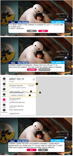
LG 32LK610BPUA, LG 32LK610BBUA LCD TVs – How to upgrade the software, fault checking method

  Software update procedure USB (1) Insert the USB memory Stick to the USB port (2) Automatically detect the SW Version and show the bel...