Wednesday, 23 October 2019

How to disassemble Asus Zenphone 2 - How to replace the screen


Asus Zenfone 2 Display Assembly Replacement
The original screen has the following code stamped on the back of the display: "TL055VDXP34-00".
The first replacement display assembly (did not work) had the following code: "TLD55VVXP31-00".
The second replacement assembly (did work) had the following code: "TL055VDXP34-00".
On that basis, it is suggested  that the first unit I received was an earlier model, and was the incorrect part. I assume that the replacement display assembly must be model TL055VDXP34-00
Remove back cover, sim card(s), and memory card.
NOTE: Remember to remove the one next to the camera (this might be covered by a small sticker).
This cover should remove quite easily - if you can't lift it, count those screws! There should be 14. Again - check that one by the camera that is somewhat hidden.
NOTE These screws are actually the only screws which hold the phone together. Once these are out and the cover is up, the speaker unit will fall away from the phone.
Panel removal – removal of internals
To remove the plastic panel pry it up at one end, and use a sharp blade to separate the double sided tape between the battery and the plastic panel.
NOTE: remove the double sided tape completely when I put it back together. It doesn't seem to really be necessary.
Remove the antenna cable, vibrate motor, and four other connections.
The three above the battery pop up away from the phone.
To disconnect the flat cable at the bottom of the battery you need to first remove the yellow plastic sticker covering it. Next lift the white tab to release the cable, then gently pull the cable out towards the base of the phone.
There are two types of different adhesives holding in the battery that I have encountered. One is double-sided foam tape (easy to remove). The other is some kind of self-amalgamating tape (hard to remove). Please be VERY cautious when removing the battery.
Ii is recommended heating the front side of the screen prior to completing this step (the battery tape is fixed behind the back of the screen).
The adhesive holding down the battery is located close to the side where the antennas are located (right side when looking down). To remove the battery, heat up the battery with a hair-dryer, then gently pull up away from the phone on the opposite site (left side).
NOTE: Be gentle with the small metal tabs on the edge of the battery; these are quite flimsy and will bend if used to force the battery. I removed the double sided tape completely here too, and did not replace it.
To remove the display itself you'll need to apply heat. I had a heat gun - this makes it a lot easier  but you could use a hair drier if you don't have a heat gun. For the sake of comparison - the heat gun took around 30 seconds to heat the display completely, which would take 3-5 minutes with a hair drier.
Once the adhesive behind the screen has been heated up, work your way around the edges of the screen with an opening pick or thin rigid guitar pick. The display will begin to separate from the housing.
Once mostly free, carefully lift the display cable through the hole in the top of the phone body.
Again; you're replacing this cable completely, so don't worry too much about it.
Removal of speaker grill
separate the speaker grill from the original display, clean the adhesive off, and attach it for the new screen. it easier to attach the grill to the actual phone body (rather than the display assembly)
Because of the condition of the adhesive for the screen assembly,  replace the adhesive completely. You could skip this step, but  it is worth cleaning it up.
To remove the existing adhesive  just use the sharp razor blade and worked  peeling it all off.
NOTE: This would be a good opportunity to 'test fit' the new screen (without adhesive) so you can see where the cables need to go. There is one which goes up behind the screen and through the middle of the phone, and another which goes through the top hole. The top one is a strange shape, and needs to go through sideways first.
To attach a new display
3M double sided adhesive tape to go around the edge of the new screen assembly.
NOTE: The replacement adhesive I used was 3M double sided adhesive tape (2mm) - the tape can be purchased  was around from a mobile phone repair supplies store. The tape was too wide and not thick enough, so I doubled it over.
It fit perfectly once I did that. Unless you can find thicker double sided tape which is closer to the original adhesive, I would recommend this approach.
Once the adhesive is all laid out on the phone, put the screen assembly on. start from the top and slide the top cable through the hole, then slowly worked my way down to the bottom.
NOTE: don't press too hard on the adhesive until you are sure that both cables are through to the back, and that the screen is sitting well in the body.
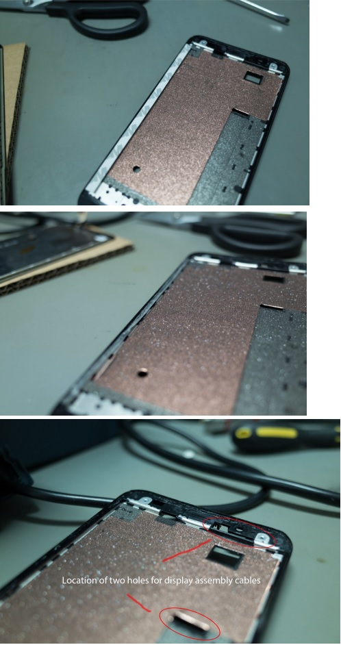
Display cable attach
Looking at the phone from the back, remove the adhesive backing from the display cable and carefully position the cable between the four black markers.
After the new screen is fixed in, start the re-assembly. This is effectively the same as disassembly, but in reverse. There were only a couple of parts that make note of:
a) Keep an eye on the display cable that comes in through the top. It got caught on the double sided tape, and needed to be pulled through.
b) You will need to use a little bit of force to mount the processor unit between the four plastic clips. Be careful when doing this.
c)  completely remove the double sided tape from under the battery and under the plastic case.
d) If you lose any of the yellow plastic cable stickers, you can borrow a piece from your old display assembly.

Friday, 11 October 2019

Wednesday, 18 September 2019

Samsung Galaxy tab 7 Battery replacement, disassembley


How to replace the battery of Samsung galaxy tab 7
Use the flat end of a metal Spurger to pry the two plastic tabs near the dock connector off the rear case. Remove the two 4.1 mm Tri-Wing screws near the adjacent edges of the dock connector.
The following steps will require you to disengage several clips (highlighted in red) around the perimeter of the rear case. The clips are delicate and fragile; proceed with caution.
Disclaimer: The Galaxy Tab we acquired already had a shattered front glass panel. However, the procedure outlined in this guide is identical for both intact/shattered front panels. nsert a plastic opening tool near the bottom left edge of the rear case. Use your plastic opening tool to gently create a small gap between the front panel and the ear panel near the bottom left edge. Run the plastic opening tool along the left side of the perimeter to create a bigger gap between the front panel and the rear panel. Insert two guitar picks into the small gap created by the plastic opening tool.
Insert the plastic opening tool into the dock connector and wedge it underneath the front panel/motherboard assembly. Thrust the plastic opening tool downwards to create a gap near the lower left corner of the front panel assembly. Insert a guitar pick into the newly created gap near the lower left edge of the Galaxy Tab.
Be careful when approaching the top left corner of the Galaxy Tab. Be sure to follow the next step carefully. When separating the front panel from the top left corner of the Galaxy Tab, be careful not to rip the microphone ribbon cable (highlighted in red in the first picture). It is extremely thin and easy to tear. Insert a plastic opening tool into the gap next to the left side of the guitar pick. Make sure to wedge it underneath the inner framework to gain the most leverage when releasing the clips. Simultaneously lift upwards and run the plastic opening tool along the top left corner of the Galaxy Tab to free the Front Panel Assembly from the retaining clips.
Slightly lift the left side of the front panel assembly to separate it from its housing within the rear panel. Do not completely lift the front panel assembly, as it is still restrained to the rear panel by clips around the top, bottom, and right sides. Doing so may cause severe damage.
Wedge the flat edge of an opening tool between the front panel and rear panel near the dock connector. Use a plastic opening tool to pry the bottom right corner out of its housing in the rear panel.


Lift and remove the front panel assembly from the rear panel.
Remove the single Phillips screw securing the battery to the motherboard.
Use the edge of a plastic opening tool to pry the battery connector straight up off its socket on the motherboard.

Wednesday, 4 September 2019

Lenovo ideapad 300 – How to disassemble – How to test the charger – How to Remove the keyboard – how to remove the HDD


Lenovo ideapad 300 Disassemble procedure
To verify a symptom, follow the steps below:
1. Turn off the computer.
2. Remove the battery pack.
3. Connect the AC adapter.
4. Make sure that power is supplied when you turn on the computer.
5. Turn off the computer.
6. Disconnect the AC adapter and install the charged battery pack.
7. Make sure that the battery pack supplies power when you turn on the computer.
If you suspect a power problem, see the appropriate one of the following power supply checkouts:
“Checking the AC adapter”
“Checking operational charging”
“Checking the battery pack”
Checking the AC adapter
You are here because the computer fails only when the AC adapter is used.
 If the power-on indicator does not turn on, check the power cord of the AC adapter for correct continuity and installation.
To check the AC adapter, follow the steps below:
1. Unplug the AC adapter cable from the computer.
2. Measure the output voltage at the plug of the AC adapter cable. See the
following figure:
Note: Output voltage for the AC adapter pin No. 2 may differ from the one you are servicing.
3. If the voltage is not correct, replace the AC adapter.
4. If the voltage is acceptable, do the following:
Replace the system board.
Note: Noise from the AC adapter does not always indicate a defect.
Checking operational charging
To check whether the battery charges properly during operation, use a discharged battery pack or a battery pack that has less than 50% of the total power remaining when installed in the computer. Perform operational charging. If the battery status indicator or icon does not light on, remove the battery pack and let it return to room temperature. Reinstall the battery pack. If the charge indicator or icon is still off, replace the battery pack.
If the charge indicator still does not light on, replace the system board. Then reinstall the battery pack. If it is still not charged, go to the next section.
Checking the battery pack
Battery charging does not start until the Power Meter shows that less than 95% of the total power remains; under this condition the battery pack can charge to 100% of its capacity. This protects the battery pack from being overcharged or from having a shortened life.
To check your battery, move your cursor to the Power Meter icon in the icon tray of the Windows taskbar and wait for a moment (but do not click it), and the percentage of battery power remaining is displayed. To get detailed information about the battery, double-click the Power Meter icon.
Note: If the battery pack becomes hot, it may not be able to be charged. Remove it from the computer and leave it at room temperature for a while. After it cools down, reinstall and recharge it.

Disassembling procedure 
Hard disk drive(HDD)
Loosen the screws 1 that secure the compartment cover. Remove the compartment cover 2.
Remove the frame fixing screws 3 .
Detach the hard disk drive connector shown by arrows 2 and 3 .
Take out the hard disk drive secured in a metal frame in the direction shown by arrow 4 .
Keyboard
Remove the screws 1.
Pull to unsnap the keyboard in the direction as shown by the arrows 2 , and then lift it up in the direction shown by arrow 3.
Pull the keyboard connector slot cover upward as shown by arrow 4, detach the keyboard cable from the keyboard connector in the direction shown by arrow 5.

Tuesday, 20 August 2019

Panasonic CTL1400 lcd tv – service mode adjustments and schematic


CTL1400 LH13 Chassis Panasonic LCD TV How to enter the service mode, service adjustments, circuit diagram
How to enter into adjustment mode
While pressing [VOLUME-] button of the main unit, press [RECALL] button of the remote control transmitter three times in a row (within 2 seconds).
Adjustment method.....Use the remote control.
“1” button...Main items Selection in forward direction
“2” button...Main items Selection in reverse direction
“3” button...Sub items Selection in forward direction
“4” button...Sub items Selection in reverse direction
Cancellation
Switch off the power with the [POWER] button on the main unit or the [POWER] button on the remote control.
Contents of adjustment mode
Value is shown as a hexadecimal number.
Preset value differs depending on models.
After entering the adjustment mode, take note of the value in each item before starting adjustment.
Note:GAMMA adjustment is for factory adjustment only. Do not change the value.
Video level adjustment
Receive 75% color bar signal
 Enter the adjustment mode and adjust the amplitude level of each signal in the following steps.
 Y signal
With [VOLUME+/-] buttons of the remote control transmitter, adjust the value appearing below YGAIN indication so that the value below MAX indication becomes B8.
 B-Y signal (TP238)
With [VOLUME+/-] buttons of the remote control transmitter, adjust the value appearing below B-Y indication so that the amplitude (white-blue) at TP238 becomes 0±0.03V.
R-Y signal (TP236)
With [VOLUME+/-] buttons of the remote control transmitter, adjust the value appearing below R-Y indication so that the amplitude (white-red) at TP236 becomes 0±0.03V
Receive 100% color bar signal at video input 1.
 Enter the adjustment mode and adjust the amplitude level of each signal in the following steps.
Y signal
With [VOLUME+/-] buttons of the remote control transmitter, adjust the value appearing below YGAIN indication so that the value below MAX indication becomes B8.
B-Y signal (TP238)
With [VOLUME+/-] buttons of the remote control transmitter, adjust the value appearing below B-Y indication so that the amplitude (yellow-blue) at TP238 becomes 0±0.03V
R-Y signal (TP236)
With [VOLUME+/-] buttons of the remote control transmitter, adjust the value appearing below R-Y indication so that the amplitude (cyan-red) at TP236 becomes 0±0.03V.
NTSC Component (525i) level adjustment
Receive 100% color bar signal at video input 1 (S terminal).
 Enter the adjustment mode and adjust the amplitude level of each signal in the following steps.
1. Y signal
With [VOLUME+/-] buttons of the remote control transmitter, adjust the value appearing below YGAIN indication so that the value below MAX indication becomes DC.
2. B-Y signal (TP238)
With [VOLUME+/-] buttons of the remote control transmitter, adjust the value appearing below B-Y indication so that the amplitude (yellow-blue) at TP238 becomes 0±0.03V
R-Y signal (TP236)
With [VOLUME+/-] buttons of the remote control transmitter, adjust the value appearing below R-Y indication so that the amplitude (cyan-red) at TP236 becomes 0±0.03V.
NTSC Component (525p) level adjustment
Receive 100% color bar signal at video input1 (S terminal).
 Enter the adjustment mode and adjust the amplitude level of each signal in the following steps.
 Y signal
With [VOLUME+/-] buttons of the remote control transmitter, adjust the value appearing below YGAIN indication so that the value below MAX indication becomes B8.
B-Y signal (TP238)
With [VOLUME+/-] buttons of the remote control transmitter, adjust the value appearing below B-Y indication so that the amplitude (white-blue) at TP238 becomes 0±0.03V.
R-Y signal (TP236)
With [VOLUME+/-] buttons of the remote control transmitter, adjust the value appearing below R-Y indication so that the amplitude (white-red) at TP236 becomes 0±0.03V.
Flicker Adjustment
1. Enter the adjustment mode and select the " FLICKR".
2. Adjust the Flicker Adjustment until the flicker displayed on the screen is minimum.
Note:Adjustment shall be done after it is made to overrun value of adjustment once as shown figure A.
Note: Make the adjustment to look for the optimum point because the level of flicker doesn´t disappear on the screen completely
MTS Adjustment
Caution: MTS adjustment shall be after the aging of 30 minutes or longer.
Apply following RF signal at Antenna input.
VIDEO : Flat field, 30 % modulation
AUDIO : 300 Hz, 100 % modulation, monaural
(70 dB ± 5 dB, 75 , P/S 10 dB)
Note: Make sure 75 us PRE-EMPHASIS is off.
Adjust "MTSIN" data (Input level) until the RMS voltage meter indicates 106 mVrms ± 6 mVrms
Select STEREO mode in the AUDIO Menu.
Set “Audio volume” DAC to “40”.
Apply following RF signal at Antenna input.
VIDEO : Flat field, 30% modulation
AUDIO : 300Hz, 30% modulation, STEREO (LEFT only)
(70dB ± 5dB, 75  OPEN, P/S 10dB)
Note: After setting 30% modulation with PL SW and NR SW off, turn PL SW and NR SW on.
Adjust "SEPAL" data (Low-level separation) until the amplitude.
Apply following RF signal at Antenna input.
VIDEO : Flat field, 30% modulation
AUDIO : 3kHz, 30% modulation, STEREO (LEFT only)
(70dB ± 5dB, 75 OPEN, P/S 10dB)
Note: After setting 30% modulation with PL SW and NR SW off, turn PL SW and NR SW on.
 Adjust "SEPAH" data (High-level separation) until the amplitude of the waveform on the oscilloscope is minimum.
7Repeat steps 3. to 6. until Low-level separation and High-level separation satisfy above-mentioned conditions.
Note: The separation must be more than 20 dB at 300Hz and 3kHz.
Hotel Mode:
Change EEPROM Address 00EF from 00 to 80.
Back to Normal Mode:
Change EEPROM Address from 80 to 00.
Note : Hotel mode can not be cleared by SELFCHECK.
Hotel Mode Setting:
Hold the “VOLUME DOWN” button inside the door of unit and
press the “TV/VIDEO” button on the remote control three times within 1 seconds.
Exiting the Hotel Mode Setting:
Press “Power” button on the remote control or on the unit.
Change address 00EF from 00 to 80
in Memory Edit Mode.
Entry to the Serviceman Mode:
Hold the “VOLUME DOWN” button inside the door of unit and
press the “RECALL” button on the remote control three times within 1 seconds.
Select main item OTP:
Press “1” or “2” button on the remote control.
Entry to the Memory Edit Mode /Some information indication:
press the “MUTE” button on the remote control for more than 3 seconds in OPT menu.
Select ADDRESS “00EF”:
 Press ”3” button on the remote control to change address.
Change DATA to “80”:
 Press “VOLUME UP/DOWN” button to change data.
 Press “6” button for 3 seconds to store the data.
TV unit go into Hotel Mode.
Exiting the Service Mode:
Press “Power” button on the remote control or on the unit.
Serviceman Mode
Entry to the Serviceman Mode:
Hold the “VOLUME DOWN” button inside the door of unit and
press the “RECALL” button on the remote control three times within 1 seconds.
Adjust Item SELECTION:
Press “1” or “2” button on the remote control.
Exiting the Serviceman Mode:
Press “Power” button on the remote control or on the unit.
OPT (Option)
Entry to the Memory Edit Mode /Some information indication:
press the “MUTE” button on the remote control for more than 3 seconds in OPT menu.
Exiting the Memory Edit Menu :
Press “1” or “2” button on the remote control.
Entry to the Memory Edit Mode:
press the “MUTE” button on the remote control for more than 3 seconds in OPT menu.
Exiting the Memory Edit Menu :
Press “1” or “2” button on the remote control.
Exiting the Memory Edit Menu :
Press “1” or “2” button on the remote control.
Exiting the Serviceman Mode:
Press “Power” button on the remote control or on the unit.
RM (Remote Control Code)
Select Remote Control Code, A or B:
Press VOL UP to set Code A.
Press VOL DOWN to set Code B.
Selected Code will be effective after turn off the unit by pressing
POWER button on the unit or remote control.
To change the Code of Remote Control :
1. Remove the cover with 3 screws
2. Short JP1 to change the Code B.
3. Close the cover.
Hotel Mode
Go into Hotel Mode:
Change EEPROM Address 00EF from 00 to 80.
Back to Normal Mode:
Change EEPROM Address from 80 to 00.
Note : Hotel mode can not be cleared by SELFCHECK.
Hotel Mode Setting:
Hold the “VOLUME DOWN” button inside the door of unit and
press the “TV/VIDEO” button on the remote control three times within 1 seconds.
Exiting the Hotel Mode Setting:
Press “Power” button on the remote control or on the unit.
POWER ON SETTING
DON’T: No setting
CH: Set Channel number when turn on the unit.
VOLUME: Set Volume level when turn on the unit.
CH/VOLUME: Set Channel number and Volume level when turn on the unit.
CH/VIDEO setting
For Channel number setting: Press “VOL UP/DOWN” button on the remote control.
For VIDEO INPUT setting : Press “VTV/VIDEO” button on the remote control.
VOLUME setting
Press “VOL UP/DOWN” button on the remote control.
VOLUME MAX
To set the volume max level:
Press “VOL UP/DOWN” button on the remote control.
Note: On-screen value is changed normally from 0 to 63 after setting. But
maximum output sound level is limited according to this setting.
OSD STOP DISPLAY
ALL:
PATTERN1:
No ON-SCREEN display
Channel number and TV/Video status are displayed when changing the channel or TV/Video.
PATTERN2: ASPECT (4:3 / 16:9) is displayed when changing the ASPECT.
PATTERN1 and PATTERN2.
PATTERN3: same as pattern 1
Channel number, TV/Video status and ASPECT are displayed when changing the channel, TV/Video or Aspect.
KEY STOP OPERATION
ALL:
All buttons on the unit (TV/VIDEO, VOL up/down, CH up/down) are
not effective.
PATTERN1: VOL up/down and CH up/down buttons on the unit are not effective.
PATTERN2: Same as PATTERN1.
PATTERN3: Same as PATTERN1
Note: All buttons on the remote control are effective in any KEY STOP
OPERATION setting.
Pressing VOL Down button on the unit for setting Hotel mode is effective.
Change address 00EF from 00 to 80 in Memory Edit Mode.
Entry to the Serviceman Mode:
Hold the “VOLUME DOWN” button inside the door of unit and press the “RECALL” button on the remote control three times within 1 seconds.
Select main item OTP:
Press “1” or “2” button on the remote control.
Entry to the Memory Edit Mode / Some information indication: press the “MUTE” button on the remote control for more than 3 seconds in OPT menu.
Select ADDRESS “00EF”:
1. Press ”3” button on the remote control to change address.
Change DATA to “80”:
1. Press “VOLUME UP/DOWN” button to change data.
2. Press “6” button for 3 seconds to store the data.
TV unit go into Hotel Mode.
Exiting the Service Mode:
Press “Power” button on the remote control or on the unit.
Serviceman Mode
Entry to the Serviceman Mode:
Hold the “VOLUME DOWN” button inside the door of unit and
press the “RECALL” button on the remote control three times within 1 seconds.
Adjust Item SELECTION:
Press “1” or “2” button on the remote control.
Press “1”
Adjust Item SELECTION:
Press “1” or “2” button on the remote control.
Entry to the Memory Edit Mode / Some information indication:
press the “MUTE” button on the remote control for more than 3 seconds in OPT menu.
Exiting the Memory Edit Menu :
Press “1” or “2” button on the remote control.
OPT (Option)
Entry to the Memory Edit Mode:
press the “MUTE” button on the remote control for more than 3 seconds in OPT menu.
Exiting the Memory Edit Menu :
Press “1” or “2” button on the remote control.
Changing Address & Data for EEPROM (in Memory Edit Menu)
Exiting the Memory Edit Menu :
Press “1” or “2” button on the remote control.
Exiting the Serviceman Mode:
Press “Power” button on the remote control or on the unit.
RM (Remote Control Code)
Select Remote Control Code, A or B:
Press VOL UP to set Code A.
Press VOL DOWN to set Code B.
Selected Code will be effective after turn off the unit by pressing
POWER button on the unit or remote control.
To change the Code of Remote Control :
1. Remove the cover with 3 screws
2. Short JP1 to change the Code B.
3. Close the cover.
Schematic Full

Monday, 12 August 2019

Q45 Samsung laptop computer troubleshooting

Samsung Q45 laptop computer troubleshooting, bios beep codes
LCD Related Troubles
The screen is dark or the colors of the screen are distorted.
* Check the connection status between the LCD module and the LCD cable, between the LCD cable and the main board LCD connector and between the LCD cable and the LCD inverter.
*  Replace the LCD cable or LCD inverter.*  Check if there is a part of the LCD that is bent or broken due to impact.
No picture appears on the screen.
*  Check the connection status between the LCD module and the LCD cable, between the LCD cable and the main board LCD connector and between the LCD cable and the LCD inverter.*  Replace the LCD cable or LCD inverter.*  Check if the System LED of the main board is blinking. (Check if it is operating or not)*  Check if the memory module is out of order.*  Check if the Power button can be normally pressed.
The LCD brightness is not adjusted.
Check if the LCD inverter is out of order.Check the BIOS version and check if the standard adapter is used.Replace the LCD cable or LCD inverter and check if it is out of order.
The LCD blinks while the system is in operation.
Check if there is a magnetic body near the touch pad button or the system or check if there is an exterior defect to the LCD or system.Replace the LCD cable or LCD inverter and check if it is out of order.Check if a standard adapter is being used (R20/R21:19V/3.16A/60W).
Main System Troubles
The system is not turned off.
Check if the AC adapter LED is lit and if the adapter is properly connected to the system.
(Check the adapter LED)
If the AC adapter is not connected, check the charge status of the battery. Even if the battery is charged, if the remaining battery charge is too low, the system may not be turned on. (As the following figure shows, press the PUSH button on the battery and check the remaining battery charge via the LEDs)Check if there are any alien substances in the Power switch. if have, change the LED.
Although system power is supplied, the system does not boot or immediately turns off after being turned on.
Since this may be a short circuit in the system, disconnect the power immediately, disassemble the system and check if there are any conducting alien objects such as a screw inside.Check the connection status between the CPU and the RHE.Replace the memory module and check if it is out of order.Reset the RTC Reset terminal next to the memory socket.
Remove RTC cable from RTC connector.
Connect the two pad of the cap for a while.
The Express card is not inserted or the Eject button does not work.
This may occur when the insulator within the Express card slot is enwrapped.Replace the Express card slot frame and check if it is out of order.
There is no sound from the speaker.
(Insert the figure of the audio jacks so that the reader can check via the figure.)
Check if the earphones or headphones are connected to the MIC jack of if there are any alien substances in the jack.
Check if the sound is muted after booting up Windows.Check the connection status of the speaker cable and check if the speaker is out of order.Check if there is a magnetic object near the speaker.
Cannot hear sound through the headphones.Check if the sound is muted in Windows.Turn the volume up.Replace the main board.
The external microphone does not work normally.
Check the audio driver settings and change them if necessary.
Selecting the "1. Front panel microphone" option activates the external MIC.
Replace the main board
The HDD is not recognized.
Check the connection status of the HDD connector. fixup HDD, check whether the system can be found. if not,change the connector on the motherboard and check again.
If the 'Operating system not found' message appears during the booting process even though the HDD is recognized by CMOS, the operating system of the HDD may be corrupted or the HDD is out of order. In this case, format the HDD and reinstall the operating system or replace the HDD with a new one.
The Touch Pad does not work or is malfunctioning.
Check the connection status of the Touch Pad FFC.Check the connection status of the Touch Pad module.
If there is no problem with the connections, replace any suspicious parts and check if they are out of order.
The battery is not charged or the battery charge LED malfunctions.
* Check the standard voltage of the adapter.
Check if the battery is defective.Replace the main board.
The LAN function does not work.
Check if the LAN cable is properly connected.Check if the LAN driver is properly installed.If the driver is properly installed, check if the LAN cable jack is out of order.Replace the main board.
The USB function does not work.
Check if the USB jack is out of order.Replace the main board.
The wireless LAN does not work normally.Check if the WLAN slide switch is in the ON position.Check if the WLAN driver is properly installed.Check if the wireless LAN antenna cable is properly connected.
Replace the main board.
The Fan does not work normally
Check if the Thermal is locked tightly.Check if the Fan cable is properly connected.
When booting up the computer
The "Invalid System Disk. Replace the Disk and then press any key" message appears.
This message may appear when the connected USB memory or CD media does not include bootable data.The "Reboot and Select the proper Boot device or Insert a bootable media in the selected Boot device and press a key" message appears.Check if the signal and power cables are properly connected to the hard disk drive.
Check if the hard disk drive is recognized in the BIOS SETUP.The operating system on the hard disk drive is corrupted. Reinstall Windows.
The "To enter BIOS SETUP, press <F2>. To continue, press <F1>." message appears.
This may happen when the BIOS settings are different from the system environment. In this case, setup the BIOS according to your system environment.Press <F2> to enter the BIOS SETUP.Check if the date and time are correct in the BIOS SETUP.Save the settings and restart the system.
The 'CMOS Checksum error’ message appears.
This message may appear when the CMOS battery of the main board is completely discharged.
In this case, replace the battery with a new one of the same type and set up the BIOS SETUP according to your system environment.
Windows boots up in safe mode.
This may happen when Windows was not shut down normally. Therefore, shut down the system by selecting Start > Turn Off Computer.This may happen when the system settings have been incompletely recognized.Run Check Disk.
Cannot boot up the computer with a USB floppy drive or from USB memory.Check if the diskette is bootable.This may happen when the booting priority of the device is low. In this case, change the booting priority in the BIOS SETUP.
When shutting down the computer
The computer is not shut down
If Windows does not end normally, you can forcibly shut down the system by pressing the Power button. If the power-saving feature is activated on the Power button, press the Power button for more than 4 seconds to turn the computer off. If the computer is then turned on again,
Check Disk is automatically run.
Windows / Screen Related Problems
The computer hangs while running a program.If the running program causes an error:
In Windows XP, press the <Ctrl>, <Alt> and <Del> key combination, select the application program and click on End Task in the Applications tab of the [Windows Task Manager] window.
In Windows 2000, press the <Ctrl>, <Alt> and <Del> key combination, select the application program or an application that does not respond and click on End Task in the [End Program] window.
If Windows does not respond, restart the computer. Restart the computer by pressing the Power button.
No picture is displayed on the external monitor.Press the Switch LCD/CRT Monitor function key and check if the screen output is output to another display device.Check if the hardware is out of order referring to the descriptions in the LCD related section of the Hardware Troubleshooting.For models with external graphics, replace the VGA board and check if it is out of order.
CD/DVD-ROM Related Troubles
Disc is not recognized or read.
Check if the ODD module and the main board are properly connected with the 50 pin connector.Replace the ODD, if necessary.
Power-Saving Mode Related Troubles
Connecting a USB device to the computer in standby mode.
If a USB device is connected to the computer in standby mode, the screen may be abnormally displayed.
You have to connect a USB device when the computer is operating normally.
A USB device is not working normally when the computer returns from standby mode.In this case, separate and reconnect the USB device.
The picture is displayed abnormally when the computer running the Command Prompt (MS-DOS)
enters standby mode and then returns from standby mode.
Press the <Alt> and <Tab> key combination to display the picture on the screen.
Device Settings Related Software Diagnosis
Check if the drivers of each of the devices are properly installed. That is, check if there are any yellow exclamation marks in the Device Manager.
Check the device driver version and check if it is conflicting with another driver. If the driver is not properly installed, install a new driver.
(The following figure illustrates the properties of the Internal GFx device driver).
Check if the program is properly installed.
Click on the Realtek Control Panel in the Control Panel and check if the function works normally.
HDD and ODD Related Problems
For an HDD, check if the HDD operates in Ultra DMA Mode 5 by selecting the Primary IDE Channel in the Control Panel as follows. If it does not, check the BIOS SETUP, reinstall the operating system or replace the HDD-FPC or HDD, if necessary.
For an ODD, check if it operates in Ultra DMA Mode 2. If it does not, check if the disc inserted into the ODD is clean. If the disc is contaminated, the access speed may slow down. If the disc is clean, check the BIOS SETUP, reinstall the operating system or ODD, if necessary.
Check if the HDD and ODD models are properly displayed. If not, check the BIOS SETUP or replace the FPC or drive, if necessary.
Windows Vista System
The operating system(OS) installed on this product is the latest version of Windows Vista, You cannot install an operating system other than vista as well as any unauthorized copy of Windows Vista.
Other operating systems (Windows 98,Windows ME,Windows 2000,Windows XP,Windows 2003 Server,UNIX and LINUX.other Windows Vista versions,etc.)other than the operating system already installed on this computer are not supported.
Installing a program that does not support Windows Vista, may cause the program to not work properly.
In this case, ask the corresponding software manufacturer about the problem . if you request the services to resolve a problem caused but incompatible software.
Other Problems
Press each corresponding button and check its operation.
System Diagnostics Card
The Diagnostics Card shows the system operations during the POST (Power On Self Test) in a2 digit hexadecimal number by connecting the cable to the 10 pin connector below the PCMCIA slot after separating the Top part. The card is used to evaluate the reason for the malfunction without disassembling the system when the system malfunctions and to test if the system operates normally after replacing a defective FRU.
Debugging Code
In general, if a defect of the circuit or part is detected during the system test, the system stops at a particular code. The error codes for each part of the system are listed in the following table.
Use of Debug card
See the debug card is connected to DEBUG connector (as following) in Main board.

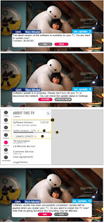
LG 32LK610BPUA, LG 32LK610BBUA LCD TVs – How to upgrade the software, fault checking method

  Software update procedure USB (1) Insert the USB memory Stick to the USB port (2) Automatically detect the SW Version and show the bel...