LG LHB655NW (LHB655NW, S63T2-S, S63S2-C, S63T1-W,
W4-2)
Total power Total: 1000W
Signal system: NTSC-PAL color TV system
Hidden key modes
MPEG HIDDEN KEY and MICOM HIDDEN KEY mode
FIRMWARE UPDATE
COPY AN UPDATE FILE TO A
MEDIA (USB OR CD-ROM)
Update File Name: LG_HB_A100M63.ROM
1)
An update file have to be copied onto the root of file system.
2) USB and CD-ROM are able to use firmware update.
Insert USB or CD-ROM
which has an update file.
2) OSD responds to the insertion event.
3) OSD is shown as below.
Caution:
Do
not turn off the power during the software update.
Note:
If the software includes the driver update, disc tray may open during the
process.
AFTER UPDATE COMPLETE
1)
When update is completed, the power will be turned off automatically in a few
seconds.
2) Turn the power back on. The system now operates with the new version.
NETWORK SOFTWARE UPDATE
Network update
notification
From
time to time, performance improvements and/or additional features or services
may be made available to units that are connected to a broadband home network.
If there is new software available and the unit is connected to a broadband
home network, the player will inform you
about the update as follows.
Option 1:
1. The update menu will appear on the screen when you turn on the player.
2. Use [> / <] to select a desired option and then press ENTER
[OK]
> Starts the software
update
[Cancel]
> Exits the update menu
and the home appears
Option
2:
If
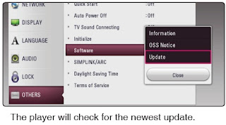
the software update is available from the update server, the “Update” icon
appears in the Home menu. Press blue (B) colored button to start the update
procedure.
Software
update
You
can update the player using the latest software to enhance the products
operation and/or add new features. You can update the software by connecting the
unit directly to the software update server.
Note:
• Before updating the software in your player, remove any disc and USB
Device from the player.
• Before updating the software in your player, turn the player off and
then turn it back on.
• During the software update procedure, do not turn off the player or
disconnect AC power, or do not press any button.
• If you cancel the update, turn off the power and turn it on for stable
performance.
• This unit cannot be updated to previous software version.
1. Check the network connection and settings.
2. Select [Software] option in the [Settings] menu then press ENTER .
3. Select [Update] option, and press ENTER
The
player will check for the newest update.
Note:
• Pressing ENTER while checking for the update will end the process.
• If there is no update available, the Message, “No update is found.”
appears. Press ENTER to return to the [Home Menu].
4. If newer version exists, the message “A new update was found. The update
takes a few minutes. Do you want to update?” appears.
5. Select [OK] to start update.
(Selecting [Cancel] will end the update.)
6. The player starts downloading the newest update from the server.
(Downloading will takes several minutes depending on your home network
condition)
7.
To update software the next time, the software update procedure has to be
started from the beginning again.
Caution:
Do not turn off the power during the software update.
Note:
If the software includes the driver update, disc tray may open during the
process.
8. When update is completed, the power will be turned off automatically in a
few seconds.
9. Turn the power back on. The system now operates with the new version.
Note:
The Software Update function may not work properly depending on your
internet environment. In this case, you can obtain the latest software from the
authorized LG Electronics Service Center then update your player.
Troubleshooting
NO
POWER PROBLEM
No power problem occurs when you power on the unit.
1-1. Fuse & Bridge diode
1-1-1. Solution
Replace
F901, BD901 on SMPS board.
1-1-2. How to troubleshoot (Countermeasure)
1) Look at the physical of fuse F901.
2) Check the bridge diode BD901.
No
power problem occurs when you power on the unit.
1-2. VFD, 14 VA, 5.5 VA
1-2-1. Solution
Replace
D922, D923, D924, D925, D926, D927, IC901.
1-2-2. How to troubleshoot (Countermeasure)
Case 1) FLD abnormal: Check D950, D951, ZD951, ZD952, FR950 and replace it.
Case 2) 5.5 VA abnormal: Check D952, D953 and replace it.
Case 3) 14 VA abnormal: Check D955, D956 and replace it.
Case 4) All voltage abnormal: Check IC901 and replace it.
NO BOOTING WHEN YOU TURN
THE UNIT ON, NO MESSAGE ON FRONT PANEL
When you turn on your set, it will blank / no message on front panel, and
stand-by led no working.
2-1. IC155 (No 3.3 VA)
2-1-1. Solution
Replace IC155 on MAIN board.
2-1-2. How to troubleshoot (Countermeasure)
1) Please check 3.3 VA of IC101.
2) If 3.3 VA is abnormal, please check 5.5 VA of IC155 pin1.
3) If 5.5 VA is OK, but 3.3 VA is abnormal, replace IC155.
When you turn on your set,
it will blank / no message or Welcome on front panel, and it will not boot-up.
2-2. IC156 System 3.3 V (No System 3.3 V)
2-2-1. Solution
Replace IC156 on MAIN board.
2-2-2. How to troubleshoot (Countermeasure)
1) Please check 5.5 VA of IC156 pin3 (VIN).
2) If 5.5 VA is abnormal, please check SMPS 5.5 VA.
3) If 5.5 VA is OK, but 3.3 V is abnormal at the IC156 pin6 (VOUT), replace
IC156.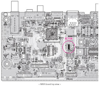
When
you turn on your set, it will blank / no message or Welcome on front panel, and
it will not boot-up.
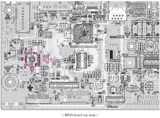
2-3. IC151 (No 1.2 V & 1.5 V)
2-3-1. Solution
Replace
IC151 on MAIN board.
2-3-2. How to troubleshoot (Countermeasure)
1) Please check 1.2 V & 1.5 V of IC151 on MAIN board.
2) If 1.2 V voltage doesn’t come out, check IC151 pin22 (VCC 5.5 VA).
If 1.5 V voltage doesn’t come out, check IC151 pin9 (VCC 5.5 VA).
If there is no 5.5 V, please check 5.5 VA from SMPS.
3) If 5.5 VA input is normal, first of all check DC15_12_CTRL is high (IC101
pin24).
If DC15_12_CTRL is high, check R159 and if there’s no defective component then
please replace IC151.
4) After changing it, if the set is still not booting :
- Check 1.2 V, 1.5 V, 3.3 V is normal. (please refer to other sections of this
guide)
- Check Crystal X501 refer to item 2-4.
- Check NAND Flash IC (IC503) refer to item 2-5.
- Check DDR IC (IC502) refer to item 2-6.
- Check MT8563 IC (IC501) refer to item 2-7.
When
you turn on your set, it will display “WELCOME” on front panel, and it will not
boot-up normally.
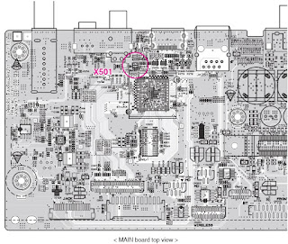
2-4. X501
2-4-1. Solution
Replace
X501 on MAIN board.
2-4-2. How to troubleshoot (Countermeasure)
1) Please check the soldering status of 27 MHz crystal (X501).
2) Please check the frequency of 27 MHz crystal (X501).
3) If the crystal doesn’t oscillate, replace X501.
4) After changing it, if the set is still not booting :
- Check NAND Flash IC (IC503) refer to item 2-5.
- Check DDR IC (IC502) refer to item 2-6.
- Check MT8563 IC (IC501) refer to item 2-7.
When
you turn on your set, it will display “WELCOME” on front panel, and it will not
boot-up normally.
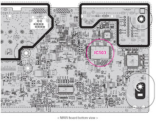
2-5. IC503 (NAND FLASH MEMORY)
2-5-1. Solution
Replace
IC503 on MAIN board.
2-5-2. How to troubleshoot (Countermeasure)
1) Please check physical status of IC503 on your eyes.
2) Check the VCC (3.3 V) of IC503 and if it’s normal, please replace IC503.
(Please make sure IC503 has proper program.)
3) After changing it, if the set is still not booting :
- Check DDR IC (IC502) refer to item 2-6.
- Check MT8563 IC (IC501) refer to item 2-7.
When
you turn on your set, it will display “WELCOME” on front panel, and it will not
boot-up normally.
2-6. IC502 (DDR3 MEMORY)
2-6-1. Solution
Replace
IC502 on MAIN board.
2-6-2. How to troubleshoot (Countermeasure)
1) Please check 0.75 V of DDR3_VREF. (between C5C2 and R5C3)
Please check 1.5 V of IC502.
2) If it doesn’t work even though IC151, IC156 are no problem,
IC502 (DDR memory) could have problem.
3) After changing it, if the set is still not booting :
- Check MT8563 IC (IC501) refer to item 2-7.
When
you turn on your set, it will display “WELCOME” on front panel, and it will not
boot-up normally.
2-7. IC501 (MPEG IC)
2-7-1. Solution
Replace
IC501 on MAIN board.
2-7-2. How to troubleshoot (Countermeasure)
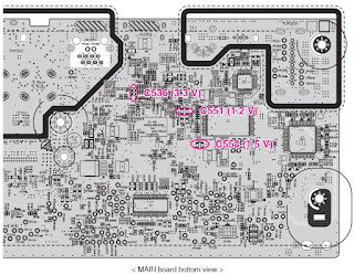
1) Please Check 1.2 V of C551 on MAIN board.
Please Check 3.3 V of C536 on MAIN board.
Please Check 1.5 V of C554 on MAIN board.
2) If it doesn’t work even though IC151, IC156 are no problem,
IC501 MT8563 could have problem.
WIRED
NETWORK CONNECTION ERROR
When you connect online service (like You-tube or Netflix2.1) through the wired
LAN,
the “no connection“ message appears.
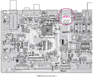
3-1. JK251 (ETHERNET JACK)
3-1-1. Solution
Replace
JK251 on MAIN board.
3-1-2. How to troubleshoot (Countermeasure)
1) Check you internet connection. Make sure it connect properly to modem or
router.
2) If internet connection OK, please check the Ethernet Jack (JK251).
3) If there is soldering problem, please re-soldering pin JK251.
4) If after re-soldering problem still occurs, replace JK251.
5) If problem still occurs after change JK251, check MT8563 IC (IC501). Refer
to item 2-7.
BAD
HDMI VIDEO / AUDIO OUTPUT
When unit is connected to HDMI TV using HDMI cable, picture shows bad color, no
output or mixed
color on the screen. But component output is OK.
4-1. JK252 (HDMI JACK)
4-1-1. Solution
Replace
JK252 (HDMI Jack).
4-1-2. How to troubleshoot (Countermeasure)
1) Check JK252 pin soldering.
2) If there is short soldering on pin JK252, re-soldering pin JK252.
3) If problem still occurs, check HDMI data.
- If all data OK, replace JK252.
- If data NG, check set on BD mode :
Replace IC501
NO
AUDIO FROM SPEAKER
When unit is connected to speaker, no audio from speaker.
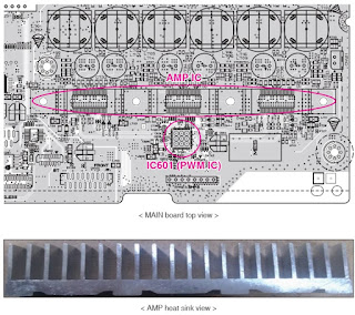
5-1. IC601 (PWM IC)
5-1-1. Solution
Replace
IC601 (PWM IC).
5-1-2. How to troubleshoot (Countermeasure)
1) Check IC601 pin soldering.
2) If there is short soldering on pin IC601, re-soldering pin IC601.
3) If problem still occurs, check AMP IC (IC700, IC701, IC702).
- Check IC700, IC701, IC702 pin soldering.
- If soldering ok, check the AMP heat sink :
Replace IC700, IC701, IC702.
NO
USB
When unit is connected to USB, no audio and video from SET.
6-1. IC501 (MT8563)
6-1-1. Solution
Change
IC501 (MT8563).
6-1-2. How to troubleshoot (Countermeasure)
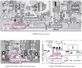
1) MAIN board : Check CN104 connector and FFC cable.
JACK board : Check CN202 connector.
2) If there is short soldering on CN104, re-soldering CN104.
If there is short soldering on CN202, re-soldering CN202.
3) If problem still occurs, check 5 V (CN104 pin11 ~ pin15).
- If no output, check MAIN board IC154.
- If OK, check D+, D- signal.
- If there is no signal, replace IC501
BT
CONNECTION ERROR
When you connect Wireless connection(like mobile phone, multi-room SPK, etc)
through the BT,
the “BT ERROR“ message appears.
7-1. BT module
7-1-1. Solution
Replace
BT module on Main chassis.
7-1-2. How to troubleshoot (Countermeasure)
1) Check your BT device. Make sure that BT function is on-state.
2) If it is OK, please check the CN252.
3) If there is soldering problem, please re-soldering pin CN252.
4) If after re-soldering problem still occurs, replace BT module.
5) If problem still occurs after change BT module, check MT8563 IC (IC501).
Refer to item 2-7
SA
RESET procedure
PURPOSE
In order to insert the new SA adjustment values, it needs clearing SA initial
values of the flash memory.
2. REQUIRED SA RESET
-
After changing traverse.
- After changing main board assembly.
- After changing main board flash IC.
3. SA RESET PROCEDURE


